USER’S MANUAL__________________________________________________________________
354 _________________________________________________________________ M211322EN-D
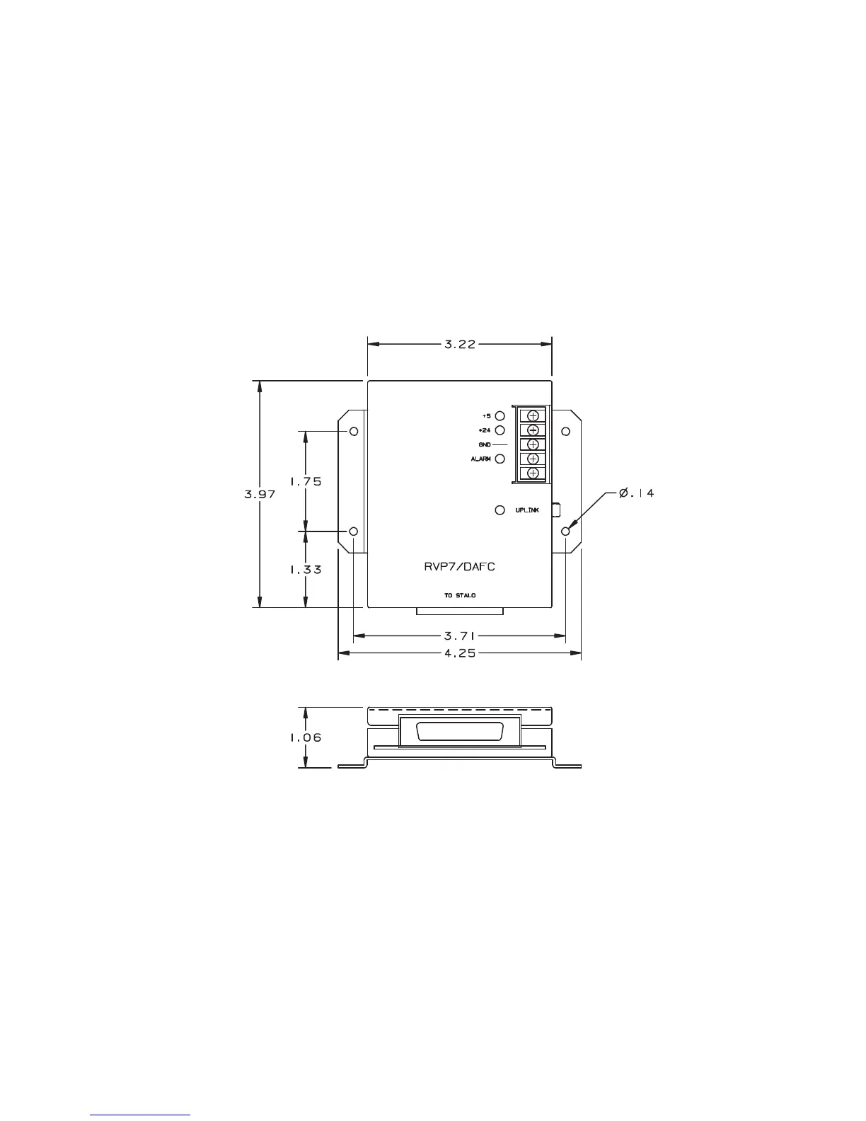
+5 VDC is all that is required to run the DAFC. If you want to supply the
STALO power through the ribbon cable between the DAFC and STALO,
connect the +24 VDC pin to a suitable power supply. Otherwise, power the
STALO directly.
The DAFC outputs up to 24 TTL lines to the STALO digital
control/interface. Since these are TTL, the DAFC should be mounted
within 30 cm of the STALO, if possible. For details on the DAFC,
including pin assignment examples for some commercial STALO, see the
RVP900’s Installation chapter (xref TBD).
0916-204
Figure 57 View of DAFC Module
B.6 Optional TDWR Custom Back Panel
The RVP900 can be supplied with a custom back panel that connects to the
specific electrical signals of the FAA Terminal Doppler Weather Radar
(TDWR). The back panel connects to the two IFDR 51-pin micro-D I/O
connectors using a pair of breakout cables shown in Table 17 on page 347.
 Loading...