Appendix F ___________________________________________________ RCP902 WSR98D Panel
VAISALA______________________________________________________________________ 459
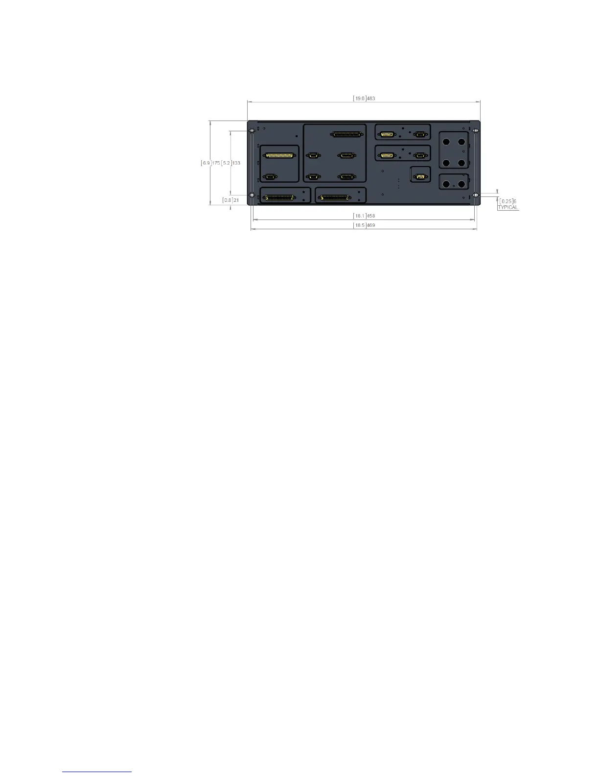
0916-023
Figure 78 RCP902 WSR98D Connectors (Modify without
dimensions)
F.6.4 Modifications on RCP902 WSR98D
Panel
The following modifications have been made to the RCP902 WSR98D
panel from the RVP8/RCP8 ORDA panel:
- J5, J6, J16, J17, J18-A, J19, J24, and J25 connectors have been
removed and their functions obsoleted
- All the connectors on the back side (*-B) have been removed
- J18 connector has been added for external power
F.7 Electrical Interfaces
There are several classes of signals for the RCP902 WSR98D panel. The
signal descriptions have a format to identify relational information.
- Signals have pull-up /down depending on initial state and to maintain
level during boot conditions
- RS-485 signals:
- Outputs have a 5 V unidirectional TVS device
- Inputs have 15 V bidirectional TVS device
- Inputs have Termination resistors on input to buffer
- TTL signals have a 5 V unidirectional TVS device
- BNC Test Point Outputs:
- Signal can drive a 50, 5 V signal
 Loading...