Chapter 2 _______________________________________________ Introduction and Specifications
VAISALA_______________________________________________________________________ 39
The uplink input from the RVP902/main board provides the timing for
multiplexing the burst pulse sample with the IF signal. In addition, it is
used to set the AFC DAC or digital output level, and to perform self-tests.
The sampling clock in the IFDR is selected to be very stable. The sample
clock serves a similar function to the COHO on a traditional Klystron
system; it is the master time keeper. The IFDR sample clock is used to
phase lock the entire RVP900; the Rx, Tx, miscellaneous I/O are all phase
locked to the IFDR sample clock.
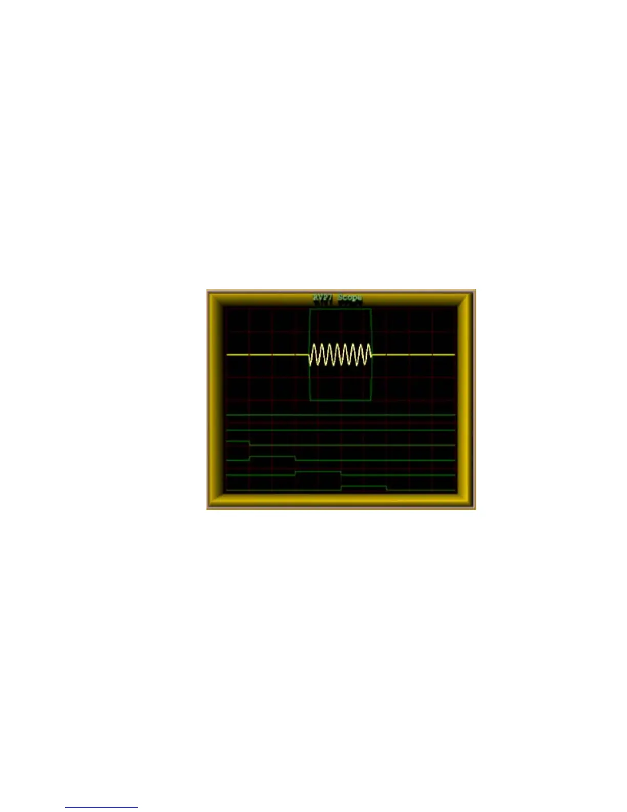
2.8.2 Burst Pulse Analysis for
Amplitude/Frequency/Phase
0916-010
Figure 12 Burst Pulse Analysis for Amplitude/Frequency/Phase
The burst pulse analysis provides the amplitude, frequency, and phase of
the transmitted pulse. The phase measurement is analogous to the COHO
locking that is performed by a traditional magnetron radar. The difference
is that the phase is known in the digital technique, so that range de-aliasing,
using the phase modulation techniques, is possible. Amplitude
measurement (not performed by traditional radars) can provide enhanced
performance by allowing the “I” and “Q” values to be corrected for
variations in the both the average and the pulse-to-pulse transmitted power.
In addition, a warning is issued if the burst pulse amplitude falls below a
threshold value.
The burst pulse data stream is first analyzed by an adaptive algorithm to
locate the burst pulse power envelope (for example, 0.8 μsec). The
 Loading...