Appendix G_______________ RVP900 Specification for ASR9-WSP with RCP903 ASR9-WSP Panel
VAISALA______________________________________________________________________ 497
G.7.11 J7, Power Interface (DC)
The power supply sub-system is designed with the following assumptions
about the input power source.
- Input Voltage: Nominal 24V ±4V
- Maximum Power Consumption: 24W
- Maximum input noise 1.0Vp-p max at 50-120 Hz, 100 mVp-p max
120-300 kHz
- Low Voltage Directive Compliant (SELV)
- Panel power connector is a DB9-M. Power cord should have a female
DB9 connector, DB9-F
- Cable to power connector should use 18-gauge wire with power and
ground twisted. If the cable is not shielded a ferrite should be added
as close to the connector as possible with the cable looped through
twice.
G.8 ASR9 RIM Software API
The original RxNet7 Radar Interface Module (RIM) API functionality has
been ported to the RVP902 Processor and modified to use the new RCP903
ASR9-WSP Panel Ethernet Interface for control and status functionality.
In addition, to the RIM commands that allow manufacturing test and debug
have been added to supplement the operational software commands.
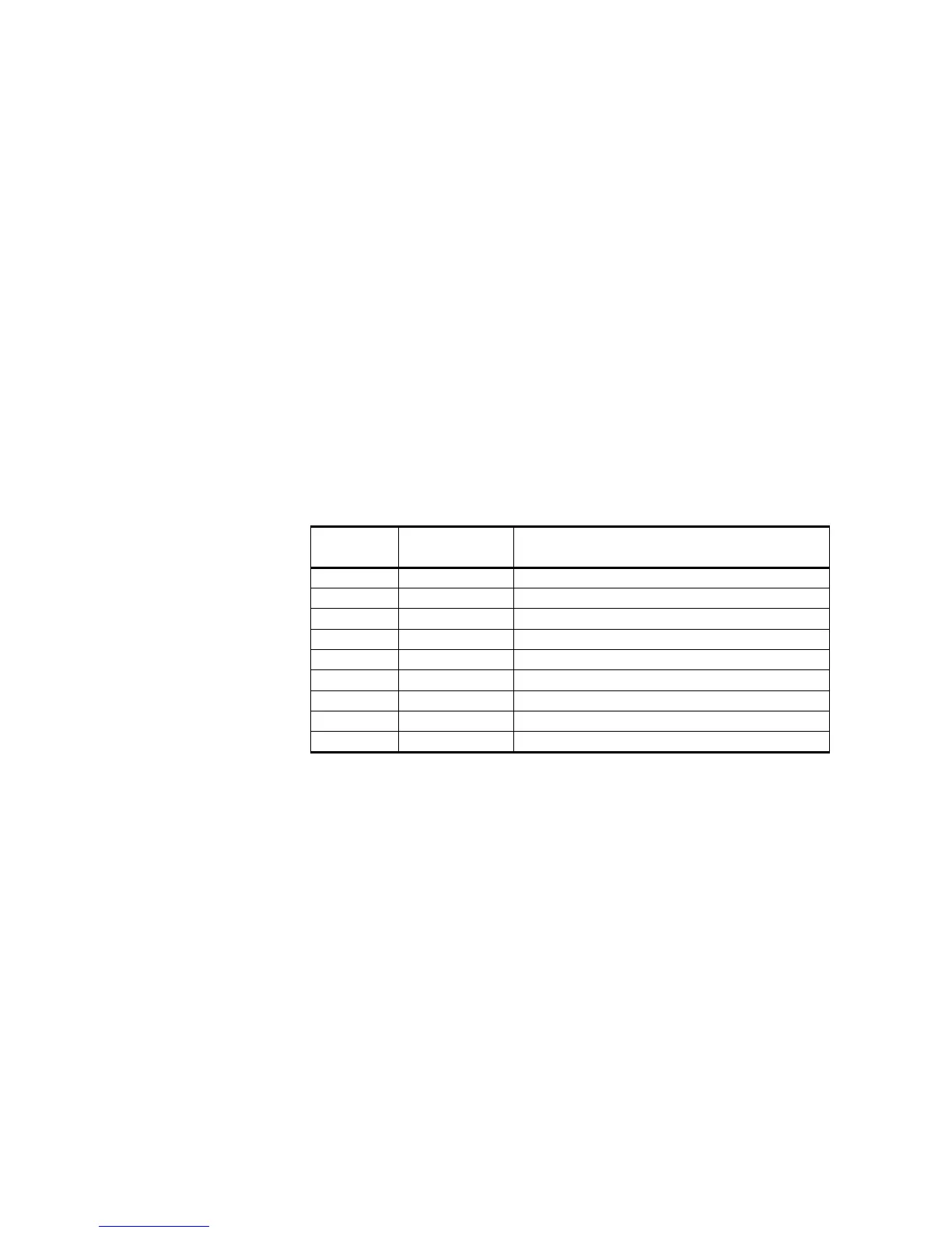
Table 47 Pin-out for J7 Power Input
J6 Pin
Number
Signal Name Description
1 PWR_IN 24V nominal input power
2 PWR_IN 24V nominal input power
3NC
4 PWR_RETURN Return path (ground) for input power
5 PWR_RETURN Return path (ground) for input power
6 PWR_IN 24V nominal input power
7 PWR_IN 24V nominal input power
8 PWR_RETURN Return path (ground) for input power
9 PWR_RETURN Return path (ground) for input power
 Loading...