Startup Procedure and Test Run
4
4.2 Keypad: Names and Functions
YASKAWA SIEPYAIH6B01A HV600 AC Drive Bypass Technical Reference 121
Symbol Name Description
D Mode display area
Shows the name of the current mode or screen.
E
Alarm codes and status messages
display area
Shows an alarm code or message about bypass status.
Refer to page 517 for more information about status messages.
F
Frequency reference source
indication
Shows the current frequency reference source.
• KPD: keypad
• AI: analog input terminal (terminals A1 or A2)
• COM: serial communications
• OPT: option card
G Data display area
Shows parameter values, monitor values, and details of the results of operations.
H Function keys 1 to 3 (F1 to F3)
The function names shown in this area will change when the selected screen changes. Push one of the function keys to
on the keypad to do the function.
I
Alarm and message texts display
area
Shows a fault, minor fault, alarm, or error name and message text.
Note:
When the drive must show an alarm and a message on the keypad at the same time, the keypad will switch between the
alarm code and message text in 2-second intervals.
J
HOA mode or alternative Run
command source indication
• OFF: The bypass is operating in OFF Mode.
• AUTO: The bypass is operating in AUTO Mode.
• HAND: The bypass is operating in HAND Mode.
• JOG: The bypass is operating in JOG Mode.
• EMOV: The bypass is operating in Emergency Override Mode.
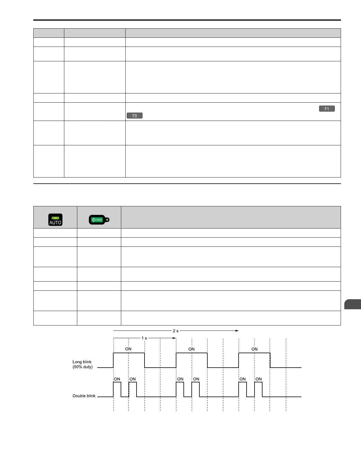
◆ AUTO LED and HAND LED Indications
Table 4.3 AUTO LED and HAND LED Indications
AUTO LED
HAND LED
Status
OFF OFF OFF Mode
OFF ON HAND Mode
OFF Long blink (50% duty) HAND Mode
• When the Frequency Reference is 0 or during deceleration
• During PI Sleep
OFF Double blink HAND Mode
When you clear the Run command and enter the Run command again during the time set in C1-02 [Deceleration Time 1]
ON OFF AUTO Mode
Long blink (50% duty) OFF AUTO Mode
• When the Frequency Reference is 0 or during deceleration
• During PI Sleep
Double blink OFF AUTO Mode
When an MFDI sends a Fast Stop signal to stop the drive
Figure 4.3 AUTO LED and HAND LED Timing Status
 Loading...