Parameter Details
5
5.7 H: Terminal Functions
YASKAWA SIEPYAIH6B01A HV600 AC Drive Bypass Technical Reference 303
■ 2E: HAND Frequency Ref or Setpoint
Setting Value Function Description
2E HAND Frequency Ref or
Setpoint
Enters the S5-05 [HAND Frequency Reference] value or the S5-06 [HAND Setpoint] value. When S5-01 = 0 [HAND Frequency
Reference Source = HAND Analog Input] and S5-03 = 0 [HAND Mode PI Selection = Disabled], the drive enters HAND
Frequency Reference. When b5-01 ≠ 0, S5-01 = 0, and S5-03 = 1 [Enabled], the drive enters HAND Setpoint.
◆ H4: Analog Outputs
H4 parameters set the drive analog monitors. These parameters select monitor parameters, adjust gain and bias, and
select output signal levels.
■ Calibrate Meters Connected to MFAO Terminals FM and AM
To calibrate the meters connected to terminals FM and AM, use these parameters:
• H4-02 [Terminal FM Analog Output Gain]
• H4-03 [Terminal FM Analog Output Bias]
• H4-05 [Terminal AM Analog Output Gain]
• H4-06 [Terminal AM Analog Output Bias]
Set these parameters where the output voltage of 10 V and output current of 20 mA are 100% of the signal level. Use
jumper switch S5 and H4-07 [Terminal FM Signal Level Select] or H4-08 [Terminal AM Signal Level Select] to select
the voltage output and current output.
No. Name Range Default
H4-02 Terminal FM Analog Output Gain -999.9 - +999.9% 100.0%
H4-03 Terminal FM Analog Output Bias -999.9 - +999.9% 0.0%
H4-05 Terminal AM Analog Output Gain -999.9 - +999.9% 50.0%
H4-06 Terminal AM Analog Output Bias -999.9 - +999.9% 0.0%
H4-07 Terminal FM Signal Level Select
0: 0 to 10 Vdc
2: 4 to 20 mA
0
H4-08 Terminal AM Signal Level Select
0: 0 to 10 Vdc
2: 4 to 20 mA
0
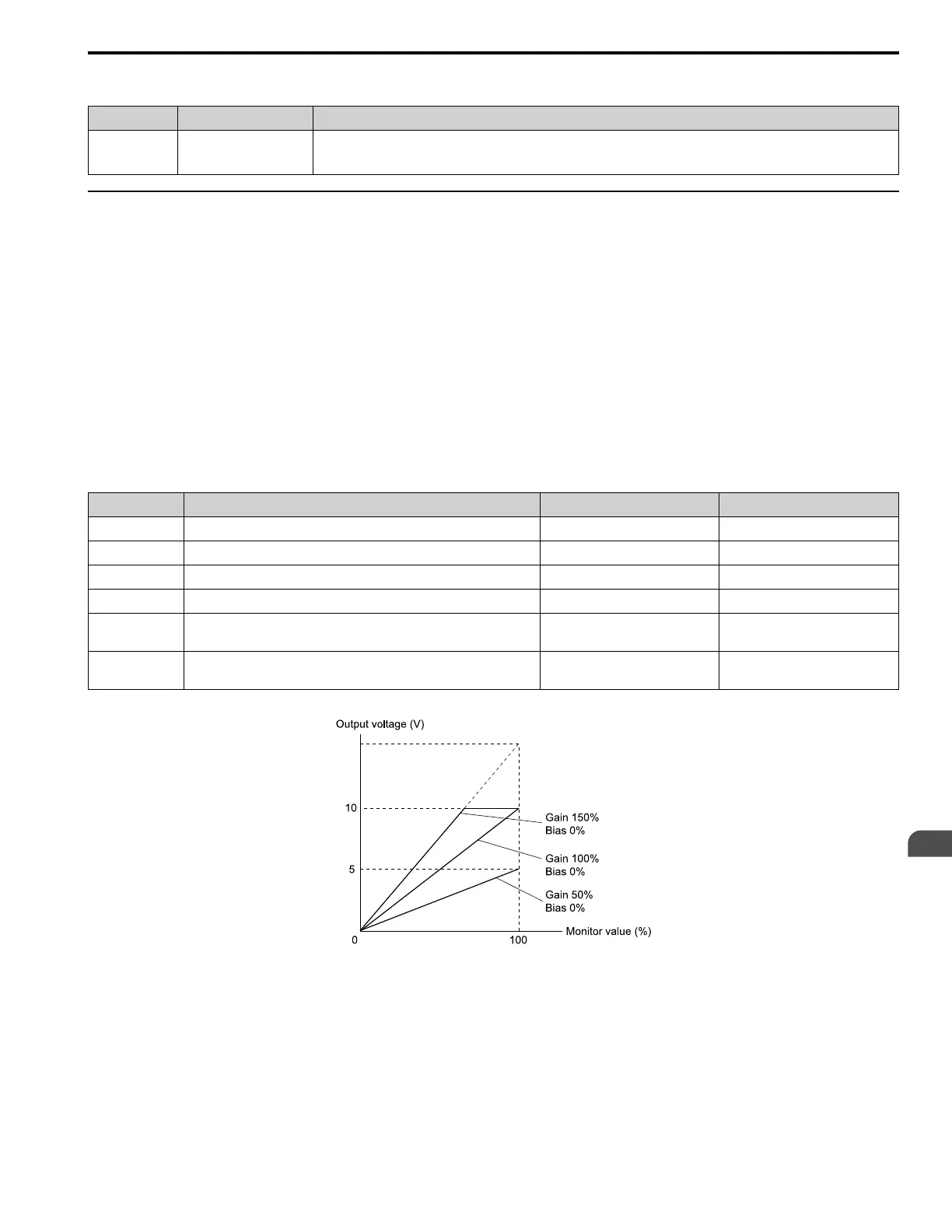
Figure 5.63 and Figure 5.64 show the gain and bias when H4-07 = 0 [0 to 10 Vdc] and H4-08 = 0 [0 to 10 Vdc].
Figure 5.63 Analog Output Gain/Bias Configuration Example 1
For example, when the parameter value set to analog output is 0, and a 3 V signal is output to terminal FM, H4-03
[Terminal FM Analog Output Bias] is set to 30%.
 Loading...