$GYDQW
&RQWUROOHU8VHU¶V*XLGH
6HFWLRQ 3URFHVV&RQWURO
3BSE 002 415R701 Rev A 1-93
When a dedicated station is used for programming, it can be connected, either directly to the
controller to be programmed, or indirectly via another controller in the communications
network. For remote access, the public telephone network can be used.
Signals are represented in engineering units throughout the whole application program.
This facilitates the configuration work, especially in connection to arithmetic operations. It also
simplifies reading and understanding of the graphical documentation of the application
program.
Scaling of an I/O signal from an electrical variable, for example, 4 - 20 mA, to a variable
expressed in engineering units is made in the data base for the point.
7\SH&LUFXLWV
To boost application programming productivity even further, the engineering stations support
the use of type circuits, that is, control solutions that are repeated frequently in an application
area or in a specific application project. For instance, a type circuit may comprise all the
functions required to control motors of a certain type, or pumps, valves, temperature loops, and
so on, including all the necessary controller data base definitions for I/O and operator
communication.
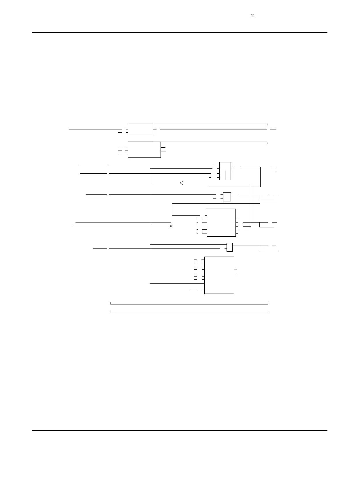
)LJXUH ([DPSOHRI$XWRPDWLF$03/'RFXPHQW3ULQWRXW
PC7
1
1
2
3
4
5
1
PC7
C
C
C
C
BUSY
REPNO
ERR
FIRST
LAST
FF
NODE
BUS
PRID
>ACT
<
PRINT(1,1,72)
5
6
7
=DO1.1/RUNNING
P
PCPGM(40,7)
RUN
ON
R
5
1
2
D=0
CONTRM(250,3,0)
ON RUN
>SINGLE MODP
5
D=1
D=0
D=0
1
2
3
6
=DI1.6/MOTOR_STOP
=DI1.6/MOTOR_START
=DI1.1/START
=AI1.3/MOTOR_CURRENT
CURRENT_WARNING
CURRENT_LIMIT
=DI1.7/ALARM_ACKNOWLEDGE
=DO1.5
IND_MOTOR-START
=AO1.4/
=DO1.6
=DO1.18
ALARM_CURRENT LIMIT
IND_MOTOR_CURREN
IND_CURRENT_WARNING
P
P
P
P
20
1
20
21
22
40
41
I>=H2
I>L1
I<=L1
COMP-R(2,1)
I
HHYS
H1
H2
LHYS
L1
I>=H1
I<H1
+
R
1
2
S
R4
1
1
1
1
3
3
D=0.000
D=0.000
D=0.00
D=100.000AmD=100.000Amp
D=5.000Amp
60
≥1
&
1
2
11
12
EXECUTION ORDER; 1 2 3 4
D=’HIGH MOTOR 1
F=1
F=1
F=1
F1
F1
F1
2
3
3
D=95.000Amp