Home
ABB
Controller
Advant Controller 450
ABB Advant Controller 450 User Manual
5
of 1
of 1 rating
564 pages
Give review
Manual
Specs
To Next Page
To Next Page
To Previous Page
To Previous Page
Loading...
Advant
®
Controller 4
50
User’
s Gui
de
Sectio
n 5.5.10
User
Repair
3BSE 0
02 415R701
Rev A
5-59
T
able
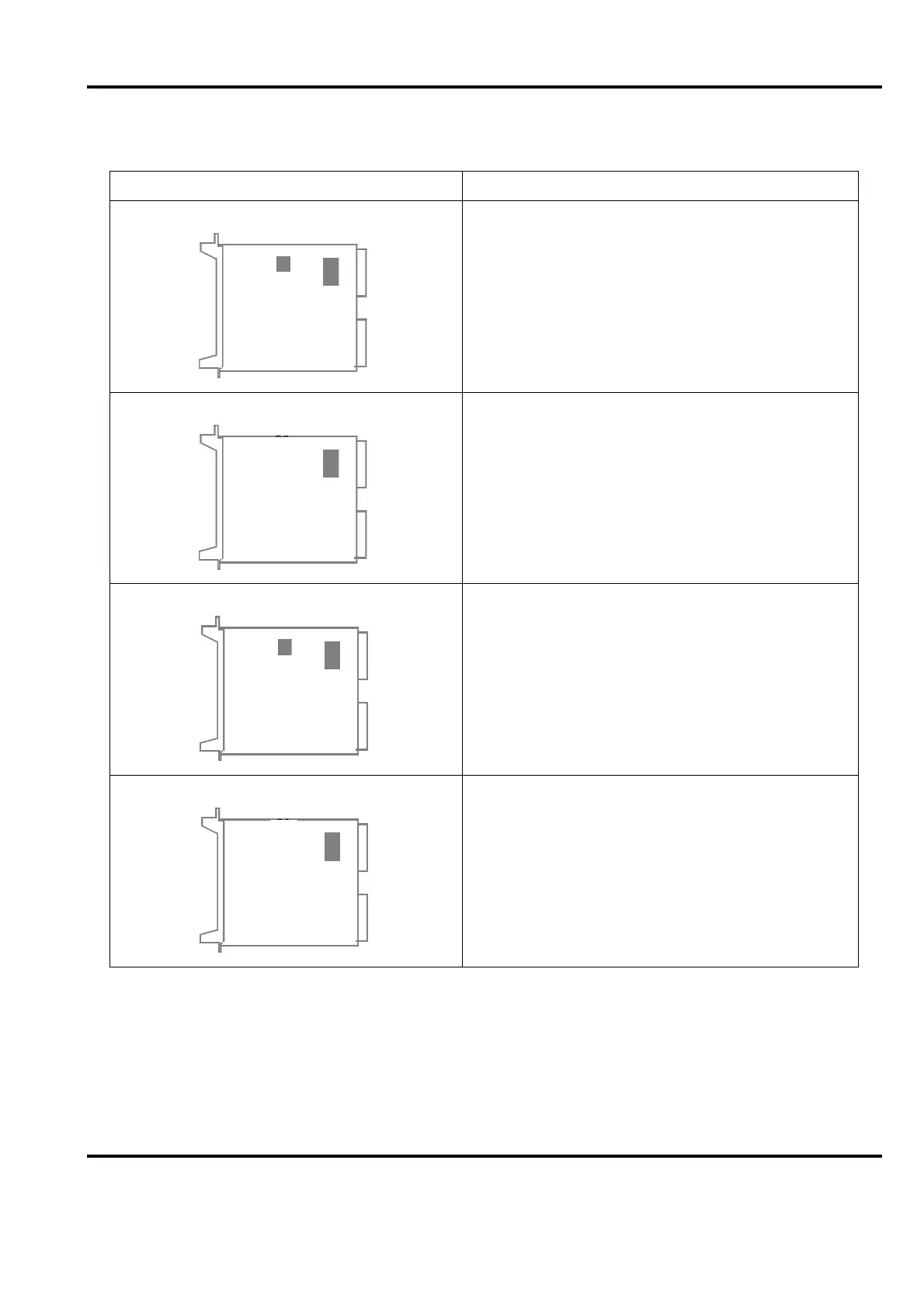
5-2.
Replacement Asp
ects of Ind
ividual B
oar
d T
ypes, S10
0 I/O
Board type - Jumpering
Comments
DSAI 130
On-l
ine replac
ement poss
ible
DSAI 130A
On-l
ine replac
ement poss
ible
DSAI 133
On-l
ine replac
ement poss
ible
DSAI 133A
On-l
ine replac
ement poss
ible
S2
S1
S2
S1
S2
S1
S2
S1
410
412
Table of Contents
Default Chapter
3
Table of Contents
3
Table of Contents
12
Illustrations
21
Tables
27
General Information
31
Basic Structure
32
Manual Organization
32
Conventions
35
Terminology
42
Circuit Breaker
43
Cold Start
43
Control Network
43
Controller
43
Object Oriented Connection
44
Multi-Drop Connection
44
Lonworks
44
Insum
44
Ram
45
Product Overview
46
Example of PC Element
48
Product Versions
48
Product Structure
49
Version Designation
49
General Modularization
50
Hardware
50
Block Diagram
52
Functional Modularization
53
Interface
53
Cpu
54
General System Utilities
54
Product Variants
54
Memory
55
System Program Backup
55
Application Program Backup
56
Location of Additional Program Cards
56
Power Supply Backup of Memory
56
Basic System
57
Functional Serve
57
Program Module Contents
57
Additional PC Elements
61
Fuzzy Control
63
Masterview
63
Operator Functions Support
63
Masterbatch 200/1 Support
64
Object Support Via Advant Fieldbus 100
64
User Defined PC Elements
64
System Clock, External Clock Synchronization
65
Execution
65
Configuration
65
Free-Programmable Module
66
Power Supply
66
Start-Up
66
System Power Supply
66
Appendix C - Delivery Documentation
67
Module Utilization
70
Mains Net Filter
71
Mains Power Switch and Distribution
71
Selection Guide of Power Supply Modules
71
Voltage Regulation
72
Controller Subrack
72
Voltage Regulation in I/O Subrack
73
Backup Power Supply
74
Fusing
74
Earthing
74
Power Supply for Field Equipment
74
Process Interface
75
General Signal Paths
76
Input and Output Signal Paths
77
I/O Interfaces on a DIN Rail
78
FCI - Fieldbus Communication Interface
78
External Signal Cable
79
Connection Unit
79
Example of Connection Unit for S100 I/O
79
Internal Cable in S100 I/O
80
I/O Board (S100 I/O)
81
I/O Unit
81
I/O Module
81
Intrinsic Safety Barries
82
HART Interface
82
Principle of HART Implementation
82
HARD Interface (S800 I/O)
83
S100 I/O
84
Digital Input, Main Points
84
Digital Input Boards
84
Digital Input, Block Diagram
86
Digital Output, Main Points
86
Digital Output, Block Diagram
88
Analog Input for Standard Signal, Main Points
88
Analog Input for Thermocouple, Main Points
89
Analog Input, Board Types
89
Analog Input, Block Diagram
92
Analog Output, Main Points
93
Analog Output, Board Types
93
Analog Output, Block Diagram
95
Pulse Counting/Frequency Measurement, Main Points
95
Pulse Counting/Frequency Measurement, Board Types
95
Pulse Counting/Frequency Measurement, Block Diagram
96
Positioning, Main Points
97
Positioning, Board Types
97
Converter Connection, Main Points
97
Converter Connection, Board Types
97
S400 I/O
98
S400 I/O Units, Outline Description
98
S800 I/O
100
S800 I/O Station
101
Modulebus
101
I/O Interfaces
102
Digital Modules
103
Analog Modules
105
Pulse Counting / Frequency Measurement Modules
106
Module Termination Units (MTU)
106
Power Supplies
108
Optical Modulebus Expansion
109
Optical Modulebus Modem
109
Modulebus Optical Port
109
Communication
110
Provided Link Types
110
GCOM, Outline Description
111
Bus Extension to S100 I/O
111
Example of Electrical Redundant Bus Extension
111
Masterfieldbus, Outline Description
112
Advant Fieldbus 100, Outline Description
114
PROFIBUS-DP Outline Description
116
Network Configurations
116
LONWORKS Outline Description
117
EXCOM, Outline Description
118
Rcom
118
Multivendor Interface, Outline Description
119
Applied Communication
120
Communication Survey
120
Explanations
121
Process Control
122
Data Set
122
Application Language
122
General
122
Type Circuits
123
Principles of Application Building
125
PC Elements and Functional Units
126
Control Functions
127
Logic and Time Delays
127
Sequence Control
127
Data and Text Handling
127
Pulse Counting and Frequency Measurement
128
Reports
129
Example of Simple Report
129
Supervision
130
Measuring
130
Feedback Control
131
Motor and Valve Control, Group Start
132
Drives Integration
132
AC 400 Configuration with Drives
132
Operator's Interface
133
Maintenance Personnel
133
Variable Speed Drive Control
133
Central Operator Station Support, Adva Command, Masterview 800/1
133
Local Operator
134
MIMIC Panel
134
Local Operator's Station
134
Central Operator
135
Availability and Security
136
Printer
136
Process Outputs Behaviour at Interrupts
137
Duplication for Security
137
Diagnostics
138
Integrated Safety System
138
Run/Alarm Relay
138
LED Indicators
139
Indications in Application Software
139
System Messages and System Status
139
Diagnostic of CPU and Memory
139
Program Execution Check
140
Diagnostic of I/O Modules
140
Diagnostic of Power Supply
140
Other Diagnostics and Error Handling
140
Redundancy
141
Mains Distribution Network
141
Power Supply, 24V
141
Voltage Regulation, 5V
142
Battery and Charger
142
Processor Module
142
Processor Module - Fault Tolerance Principle
143
Network Communication
144
Gcom
144
Masterfieldbus
144
Advant Fieldbus 100
145
S100 I/O Bus Extension
145
Mechanics
146
Cabinets
146
Available Cabinet Types
146
Cabinet Features
147
Environmental Adaptation
148
Cabinet Configuration
148
Electro Magnetic Compatibility and CE-Marking
148
Subracks
150
I/O Subrack
150
Front of I/O Subrack
151
I/O Subrack Configuration
152
Submodule Carrier and Submodule
153
Carrier Module and Submodule Mechanism
153
User Interface
154
Installation
155
Site Planning Environment
155
Site Selection and Building Requirements
155
Environmental Considerations
156
Electromagnetic Compatibility
157
Temperature
157
Vibration
157
Summary of CE-Marking Aspects
158
Cabinet Floor Cover Plates
158
Cabinetry
158
Arrangement of Cabinets
158
Standard Layout and Disposition of Cabinets
159
Central Location of S100 I/O Cabinets
159
Standard Central Cabinet Configuration (Maximum)
159
Distributed Location of S100 I/O Cabinets
160
S100 I/O with Object Oriented Connection Units
161
Grounding
162
Grounding in General
162
Protective Earth
162
Grounding of Signals and Voltage Supply
162
Cables
163
Power Supply and Fusing
163
Safety Switch
164
Current Consumption and Fusing
164
Uninterrupted Power Supply
164
Process Connection
165
Connection Principles, Fusing and Voltage Distribution
165
Hazardous Applications
167
High Voltage Switch-Gear Applications
167
Lightning Stroke Protection
167
Weight and Mounting Dimensions
167
Minimum Distance to the Walls and the Ceiling
168
Transportation and Storing
169
Setup
169
Necessary Outfit
169
Safety Regulations
170
Personnel and Process Safety
170
Machine Safety
171
Warning Label Regarding ESD
171
Unpacking and Storing
172
Location
172
Arrange the Cabinets
172
Earth Line
173
Grounding of Process Cable Shields
173
Handling of Process I/O Cable Shields in a CE-Marked Cabinet
174
Grounding of Communication Cable Shields
175
Not CE-Marked Design
175
Handling of Cable Shields in a Not CE-Marked Cabinet
175
CE-Marked Design
176
Direct Grounding
176
Grounding by Capacitor
176
Cabinet
176
Communication Cable Shield Grounded by Capacitor and Ferrite Coil
177
Methods of Handling Communication Cable Shields
177
Grounding of Cable Shield, Connection Unit - I/O Board
178
Grounding of Process Signals
179
Grounding of Additional Equipment
180
Cable Routing in Cabinets
180
Individual Grounding of Process Signal
180
Assigned Space for Cables in a Cabinet
181
Cable Categories in a Cabinet
181
Power Supply Connection
182
Plant Cable Routing in OOCU Cabinet
182
Main Principle of Power Supply Connection and Distribution
183
Heating Element
184
Preparation for Start-Up
184
Electric Installation
185
Connection of Run /Alarm Relay
185
External Clock Synchronization
186
Additional Supervisory Inputs
186
Connection of External Clock Synchronization
186
Connection of Additional Supervisory Inputs
186
Functional Measures
187
Example of Bus Extension
188
Functional Jumpering
189
Process Signals
190
Address Jumpering
190
Check of the External Wiring
191
S800 I/O and S400 I/O
192
Peripheral Units
192
Supply of Peripheral Unit Without Modem
193
Short-Distance Connection
194
Long-Distance Connection
194
Long-Distance Connection of Printer
195
Connections and Grounding of Communication Cable Shields
195
Functional Measures, General
196
Printer Settings
196
Engineering Station
197
Checklists
197
Grounding Philosophy, Earthing Line System
197
Process Cabling, Shielding, Grounding, Maximum Length
198
Supply
199
Lightning Protection
199
Subrack, Connection Unit, Circuit Board
200
Cabinets, Internal Cables
201
External Cables
201
Communication, Communication Cables
202
Miscellaneous
203
Final Procedures before Start-Up
203
Shut-Down Procedures
203
Controller and I/O
204
Emergency Shut-Down
204
Safety Shut-Down
204
Manual Stop
205
Peripheral Equipment
206
Start-Up Procedures
206
Automatic Stop
206
Conditions Given by “Setup”
207
Measures by Security Means
207
Power-Up
208
Connection of Engineering Station
210
Power-Up, Circuit Breakers and Positive Indications
210
Controller System Configuration
211
Controller System Configuration in a Broad Outline
212
General
213
Dimensioning and Disposition of RAM
215
Dimensioning of the Data Base, DIMDB Command
215
Redimensioning of the Data Base
216
Dimensioning of Space for PC Program
216
Configuration/Application Building
217
Redimensioning of Space for PC Program
217
Dumping and Loading
217
Dump and Load Facilities
217
Situations Which Cause Clearing of the RAM
218
Installation of Battery for Backup of Memory
220
Configuration, Printer
221
Programmable Parameters
221
Product Verification
222
Configuration, Advant Controller 450
222
Verification of the Start
222
Servicing Tool
223
Modify Permission
224
Blocking and Deblocking of the PC Program
224
“Modify Permission” in a Control Module
224
List of some Test Facilities Provided by the Engineering Station
225
Presentation of Values in Data Base and PC Program
225
Changing of Data in the Data Base
225
Parameter Change in PC Program
225
Tuning of Feedback Control Loops
226
Use of PC Programming During Operation When Commissioning
226
Cycle Times for Advant Controller 450
226
Change of Execution Sequence for PC Elements
226
Listing of Executing Unit Status
227
Check of Process Input/Output System
227
Input Signals
228
Digital Input Signals
228
Principal Block Diagram of S100 I/O Input Channel, Test Points
228
Output Signals
229
Digital Output Signals
230
Principal Block Diagram of S100 I/O Output Channel, Test Points
230
Listing of PC Program and Data Base
231
Analog Output Signals
231
Graphic Diagram
232
Program List
232
Final Control
233
Implementation of Functions in Systems Already Operating
233
General Guidelines
234
On-Line/Off-Line
234
Data Base Dimensioning
235
Dump of Application Program
235
Additional I/O Boards
237
Preparation and Setup
237
Grounding of Connection Units
238
Extension with Redundant Processor Module
241
Extension On-Line
241
Extension Off-Line
242
Normal Installation
242
Installation with Increased Safety
242
Enlargement of the System Software
243
Power-Up Ahead of Program Loading
245
Design Considerations
247
Appropriate Hardware and Software
247
System Clock
248
Backup of Application Program
250
Number of Power Supply Units
251
Current Consumption
252
Fusing in Distribution Board
253
Network A/B
253
Fuse Dimensioning Current (FDC)
254
24 V/48 V
255
24 V
255
Interface to Application Program
257
Guidelines
258
Centralized I/O
258
Distributed I/O
258
S100 I/O System
259
Analog Inputs
259
Combined Analog Inputs and Outputs
261
Analog Outputs
261
Digital Inputs
262
Digital Outputs
263
Link Types, Hardware and Software
268
Guidelines - Communication in General
269
Location and Exploitation of Hardware
269
Masterbus 300
269
Masterbus 300E
270
Excom
270
General
272
Data Set Communication
273
Designation of Data Sets
273
Performance Considerations
273
Application Building with AMPL
274
Structuring of the Application Program
274
Heat Dissipation
278
Cabinet Ventilation
278
Heat Dissipation Permitted in Cabinets
278
Cabinets in Groups
279
Calculation of Heat Generated in a Cabinet
279
Maintenance and Repair
280
Expansion Possibilities
280
Spare Considerations
280
Memory Calculation
281
Explanation of Memory Requirement
281
Calculation of RAM Requirement
282
CPU-Optimization, Load Calculation
285
What Is the CPU to Do?
285
CPU Load Calculation
287
Additional Information for Redundant Processor Modules
288
CPU Load Calculation Methods
288
How Can an Excessive CPU-Load be Reduced?
289
I/O
289
Pc
289
Technical Data Including Capacity & Performance
290
General Technical Data, Capacity
290
Performance - General
290
Performance - Base Load
291
Load from Cyclic Functions, Overview
291
Performance - PC and Process I/O
292
Process I/O Handling
292
PC System
292
Estimated Application Functions
293
Example of Execution Times of Digital Signals
294
Subscription
295
Data Set with Masterbus 300
297
Command
297
Event Handling
297
Performance - Master View 320
298
Logging
299
Medium Log Intervals
300
Data Set Peripheral with Advant Fieldbus 100
300
Data Set and AL, AO, DI, DO with EXCOM
302
Reserve
303
Redundant Processor Modules
304
CPU Load
304
Upgrading Time
304
Memory Requirement
305
Battery Backup Time
305
Relative Time Error with Time-Tagged Events
307
Application Start-Up
317
Tutorial
317
Introduction to the Design
317
Design Procedures
318
System Definition
318
Naming
320
Example of Designation in a Feedback Control Loop
320
Application Procedures
322
Runtime Operation
323
Working Modes
323
Ordering Working Modes
324
Start Modes
324
Primary and Backup Processor Module
325
Relations between Start Modes and Working Modes
326
Manual Selection
326
First Power-Up
327
Diconfig
330
Econfig
331
Programmed Start
333
Programmed Start at Power-Fail - Power-Up
334
Programmed Start at DICONFIG
336
System Program
337
Operating System
339
Survey of Processor Module and Operating System
339
Process Communication
340
Diagnostics for the System Program
340
Application Program
341
Data Base
341
Data Area for PC Programs
342
Example of PC Element: FUNG-1V
342
Interpreter
343
Example of Function Performed by FUNG-1V
343
Execution Sequence Within an Execution Unit
345
Sequence of Execution of Execution Units
345
Function Consisting of Two Execution Units
345
Execution Sequence for an Individual PC Element
346
Execution Sequence of PC Elements
347
Resetting Execution
347
Scanning of Process Inputs
347
Data Transport
348
Reading-In Phase
348
Example of Reading-In Phase
348
Reading-Out Phase
349
Example, Reading-Out Phase
349
Data Transport between Execution Units
350
Initialization of Process Communication
351
Operating Overview
352
4Runtime Operation Menus
352
Maintenance
353
Preventive Maintenance
353
Visual Inspection
356
Air Filter
356
Backup Batteries
356
Forced Cooling
356
Error Messages
357
Halt Codes
357
System Messages
357
Reading of Halt Codes
357
Reading of System Messages
358
Fault Finding and User Repair
358
Diagnostics and Fault Announcement
359
The Controller and I/O Cabinet
359
Plant Central Fault Annunciator
359
Central Operator Station
360
24 V Supply A/B Faulty
362
Voltage Regulator Faulty
362
Backup Battery Faulty
363
Battery Charger Faulty
364
Error in CPU
364
Memory Error/Missing Card/Wrong Card
365
FPB Board out of Order
366
24 V I/O Supply A/B Faulty
367
Fan for CPU Faulty
368
Fan for I/O Faulty
369
Bus Extender Error
370
User Defined Error 1
371
CI531 Missing
372
S800 I/O Station (Redundant Fci’s)
384
S100 I/O Bus Extender
385
Fault Finding Principles
386
Typical Simple Scenario
388
A Complex Scenario
388
Fault Classification and Scheme of Measures
389
Test Equipment
389
Basic Fault Finding
389
On-Line/Off-Line Aspects
390
List of General Fault Finding Procedures and Hints
392
Location of Malfunction
392
External Factors
392
Safety at Start/Stop
392
Check of Power Supply
393
Restoring of a New Backup
393
Mains Supply and 24 V Power Supply - General Fault Finding
400
Check of Backup Power Supply
401
Check of Processor Module
401
Fault Finding by Reducing the System
403
User Repair
405
Board and Subrack Mounted Unit Exchange
405
Additional Aspects of Individual Board Types
406
Replacement Aspects of Individual Board Types (Controller Hardware)
407
Replacement Aspects of Individual Board Types, S100 I/O
411
Replacement of Redundant Processor Module
418
Replacement of Redundant S100 I/O Bus Extenders
418
Replace a Primary DSBC 174
419
Replace a Primary TC560V1/TC561V1
419
Replacement of Power Supply Unit
420
Replace a Backup DSBC 174
420
Replacement of 5 V Regulator
421
Off Line Replacement
421
On Line Replacement
421
Single SR511
422
Redundant SR511
422
Dssr 122
423
Dssr 170
423
Replacement of Backup Power Supply
424
Battery Exchange
424
Replacement of Connection Unit
425
Practical Execution
425
Replacement of Modem
426
Adjustment of Analog Input and Output Boards
426
Adjustment Possibilities on Circuit Boards
427
Channel Adjustment on DSAI 130
427
Adjustment of Zero Points, Channel by Channel
428
CMRR Adjustment, Channel by Channel
428
Full Scale Adjustment, Channel by Channel
428
Adjustment of A/D Converter
429
Adjustment of the Zero Point on the A/D Converter
429
Adjustment for Boards DSAI 130, DSAI 133 and DSAX 110
429
Adjustment of the Full-Scale Value on the A/D Converter
430
Adjustment of Symmetry (DSAI 130)
430
Adjustment for Boards DSAI 145/146 and DSAI 151
430
Zero Point Adjustment
430
Channel Adjustment on AO Board
431
Adjustment of Voltage Output
431
Adjustment of Zero Point, Channel by Channel
432
Adjustment of Current Output
432
Adjustment of the Gain, Channel by Channel
433
Adjustment of Variable Gain, Channel by Channel
433
Full Scale Voltages
433
Adjustment of Isolation Amplifier
434
Adjustment of Reference Voltage.
434
System Restart Following Maintenance Activities
434
System Restart, INIT
435
Loading of Application Program
436
CPU Load Measurement
438
Backup of System
438
Backup of Application
438
Step-By-Step Instruction
439
System Upgrade
440
Hardware Modules
441
List of Hardware Modules
441
CI531-RS-232-C Communication Interface
446
Energy Reservoir
448
Mechanical Data
449
Program Card Interface
450
Dummy Modules
454
Fan Unit
455
Controller Subrack 12 SU
457
RF540, RF541 - Modem Subrack
460
Power Supply Units
462
Fuses
464
Battery Unit
470
Sc5X0 Submodule Carriers
472
SD150 - D.C. Converter
474
SR511 - Regulator 24 V/5 V
476
Power Switch and Distribution Units
478
Distribution Unit 60 V D.C.
484
TC520 - System Status Collector
486
Appendix B RM500 Cabinet - Data Sheet
489
RM500 Cabinets - General
489
RM500 Cabinet Measurements
490
Mounting Cabinets Together
492
Mounting Cabinets to the Floor
492
Protection Rating
493
RM500 Cabinet Protection Classes
493
Available Degree of Protection Ratings for RM500
493
Permitted Power Dissipation
494
Delivery Documentation
495
Delivery Binder Content
495
Delivered Version Specification
495
Delivery Specification
495
Item Designation of Mounting Planes
497
Appendix D Item Designations
497
Cabinet with Door Removed
498
Controller Subracks
499
Item Designation in Controller Subrack 12 SU
499
Item Designation in Controller Subrack 18SU
500
Addresses in Controller Subrack 12 SU
500
I/O Subracks
501
Item Designation in I/O Subrack
501
Modem Subracks
502
Item Designation in Modem Subrack, 19 Inches
502
Item Designation in Modem Subrack, 24 Inches
502
Modem Mounted on a Bracket
502
Circuit Boards and Units
503
Numbering of Submodules and Connectors on the Front
503
Numbering of Connectors on the Rear Side
503
Connection Units
504
Connection Units, Connection and Terminal Numbering
504
Location of Connection Units on a Mounting Bar
504
Typical Internal Connection
505
Terminal Block Numbering
505
Location of Mains Units
505
Examples of Item Designation in Cabinets
506
Calculation Algorithms and Forms with Technical Data
509
Appendix E Current Consumption and Heat Dissipation
509
Current Consumption and Power Dissipation, Controller Modules
510
Current Consumption and Power Dissipation, S100 I/O Boards
511
Load Calculation Forms
515
Appendix F Load Calculation
515
Form for Memory Calculation
519
Appendix G Memory Calculation
519
Example of Halt Code Printout
523
List of Halt Codes and Corrective Actions
523
Appendix H Halt Codes
523
List of Halt Codes
524
List of Halt Codes and Corrective Actions
525
Message Coding
529
Message Types
530
List of System Messages and Corrective Actions
531
Overload
531
Task Interrupted
531
Task Killed
532
Masternet
533
List of Common Concept Numbers in System Messages
541
Appendix I System Messages
542
Appendix J Hexadecimal to Decimal Representation
557
Conversion Guide
557
Index
559
Other manuals for ABB Advant Controller 450
Product Guide
120 pages
5
Based on 1 rating
Ask a question
Give review
Questions and Answers:
Need help?
Do you have a question about the ABB Advant Controller 450 and is the answer not in the manual?
Ask a question
ABB Advant Controller 450 Specifications
General
Brand
ABB
Model
Advant Controller 450
Category
Controller
Language
English
Related product manuals
ABB Advant Controller 80
84 pages
ABB AC500
18 pages
ABB ACS550
310 pages
ABB ACS320
442 pages
ABB ACQ580
5 pages
ABB ACS150
156 pages
ABB AC 800M
230 pages
ABB ACH 400
48 pages
ABB ACH 500
117 pages
ABB AC 900F
156 pages
ABB ACS 601
88 pages
ABB ACS 400
187 pages
 Loading...


