Advant
®
Controller 450 User’s Guide
Chapter 2 Installation
2-84 3BSE 002 415R701 Rev A
8. Provide access to the desired position in the subrack by loosen the locking bar in front of
the boards.
9. Insert the I/O board carefully in the subrack without reaching the rear plane contacts.
Ensure that the board slides in the guides in the subrack.
CAUTION
At insertion, use the grounded wristband.
10. Push in the new board quickly and decisively
11. Ensure that the board contacts mate properly with the contacts in the rear plane. Screw the
locking bar in place.
12. Connect the process cables to the connection unit. Reflect upon all installation rules
regarding cable routing and grounding.
As an alternative, first make a functional verification when the process is not connected.
Then connect.
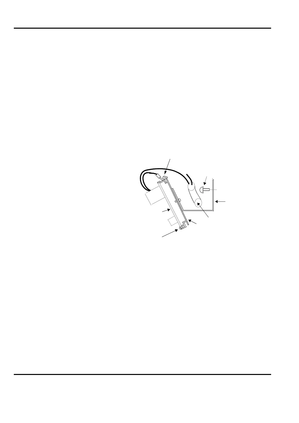
Figure 2-32. Grounding of Connection Units
Connection unit
Cable
Cable duct
Mounting rail
Thread-cutting
M6x10 screw
Self-tapping ST 3.5x9.5
(B6x9.5)
screw
Grounding
Grounding
Eventual
grounding
of signal
 Loading...


