Advant
®
Controller 450 User’s Guide
Chapter 2 Installation
2-26 3BSE 002 415R701 Rev A
You must follow the main rule: Do not ground a signal at different points in the plant.
2.2.5.8 Grounding of Additional Equipment
Treat additional power supply units of different types, aimed at load/sensor supply and modems,
and so on erected in the controller or I/O cabinet, in the following way with respect to
grounding:
• Connect the apparatus chassis (or PE terminal) to the protective ground via one of the
power distribution sockets on the power switch unit or directly to the cabinet chassis.
• Consider application-adapted grounding of power supply 0 V. If desirable, connect the 0 V
terminal to the chassis. It is preferable that you use the protective earth screw.
2.2.5.9 Spare Conductors
Spares in field cables are to be grounded within a cabinet, in case of a CE-marked design.
2.2.6 Cable Routing in Cabinets
Cables are practically routed on either side of the cabinet depending on the final destination.
The physical item destination for an actual apparatus, and thereby the connection point, appears
in the circuit diagrams and other installation drawings enclosed at delivery.
The assigned space for cables that are entered in the floor opening is shown in Figure 2-14.
For your information, the space for the factory assembled cables is also indicated in
Figure 2-14. Regard the latter cables and leads as sensitive to disturbances and keep them away
from cables coming from the plant. You will encounter these areas only when the system is
enlarged by additional equipment, for example, a circuit board and connection unit.
Plant cable routing within cabinets holding object oriented connection units (OOCU) diverge
somewhat. This is illustrated in Figure 2-15.
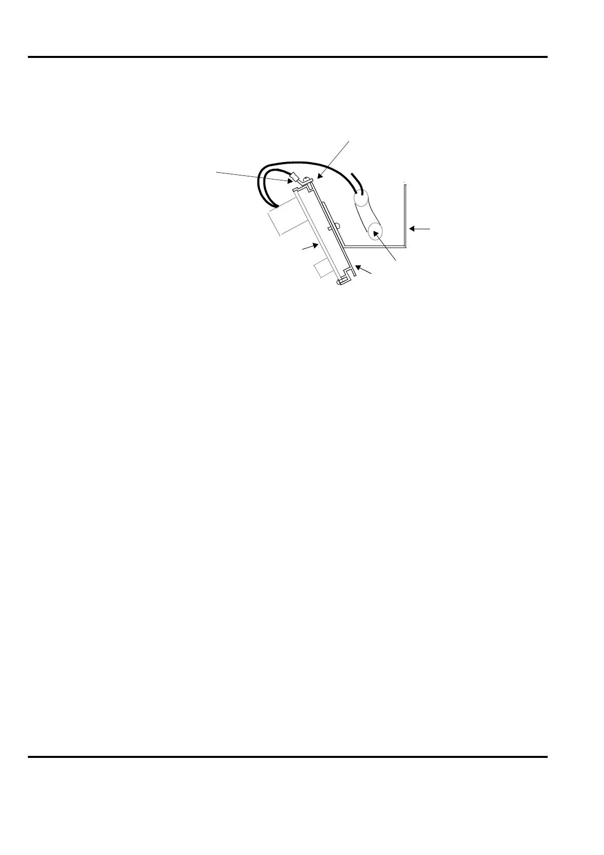
Figure 2-13. Individual Grounding of Process Signal
Connection unit
ST 3.5x9.5
(B6x9.5)
Self-tapping
screw
Cable
0 V lead
Cable duct
Mounting rail
Point of grounding
Sheet cable lug and
(used for certain cable shield connection too)
 Loading...


