Advant
®
Controller 450 User’s Guide
Section 2.1.4 Standard Layout and Disposition of Cabinets
3BSE 002 415R701 Rev A 2-5
2.1.4 Standard Layout and Disposition of Cabinets
A series of rules for mounting the controller and I/O in RM500 cabinets follows.
These configuration rules are applied when the customer has no preconceived ideas regarding
the design. This is the standard solution, which is important to know when you are planning a
control system. The complete list of rules are presented in ordering documentation.
General
• An Advant Controller 450 with I/O, ordered on one set of price lists, is designed with
cabinets that are to be placed side by side (no plates between the cabinets).
• All cabinets (single or double) sharing the same bus extension for S100 I/O (maximum
12 m) are connected to the same power switch. Exception; cabinets housing I/O with
object oriented connection units have a special arrangement, see figures below.
• An Advant Controller 450 with I/O is delivered in a number of single or double cabinets.
• Up to six cabinets, for example, three double cabinets, for the five possible I/O subracks
can be connected to the same electrical bus extension. With optical bus extension other
rules are applied.
• You can add an extra, seventh cabinet if necessary to house connection units. This cabinet
is placed to the right and cannot contain an I/O subrack. Cables with extended length have
to be used from the I/O subracks.
• An I/O subrack is not filled with more than 18 (17) in case of S100 I/O Bus Extension
redundancy) boards, two empty slots are kept as spares for the future.
• The number of boards in an I/O subrack is limited to either the 18 (17) available slots in
the subrack or the available space for connection units within the double (single) cabinet.
• In each double (single) cabinet, space for one mounting bar (for connection units) is left
unused.
• The boards are placed in the I/O subracks in the order AI, AO, DO, DI starting in subrack
no. 1.
Central Location of S100 I/O Cabinets
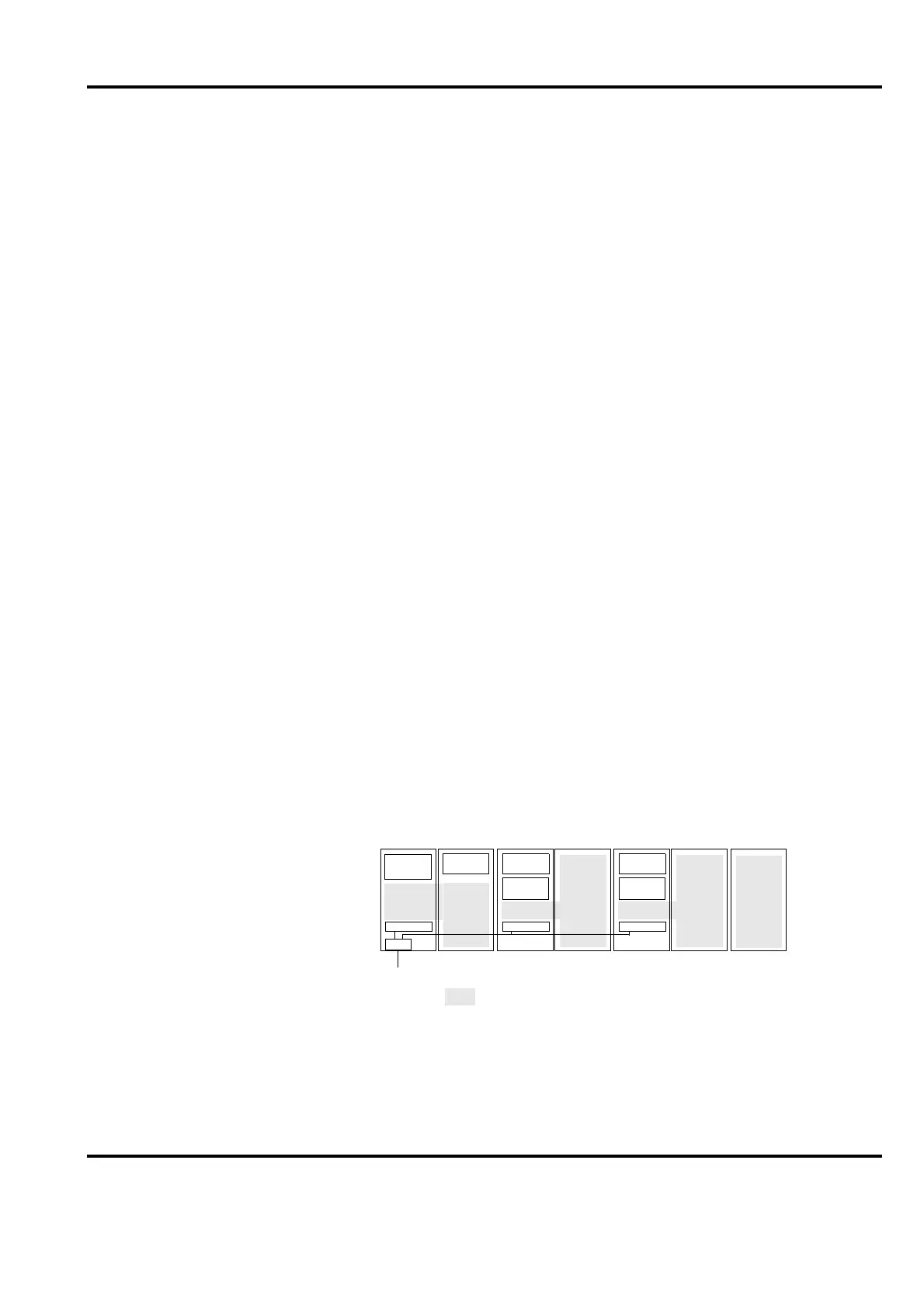
The configuration of central located cabinets is illustrated in Figure 2-1
.
Figure 2-1. Standard Central Cabinet Configuration (maximum)
PS
PS
SW
Mains
I/O 2
I/O 3
I/O 1
Conn.
units
PS Power Supply
SW Power Switch
CPU
PS
I/O 4
I/O 5
Extra
Cabinet
123
4
5
6
7
 Loading...


