Advant
®
Controller 450 User’s Guide
Chapter 5 Maintenance
5-76 3BSE 002 415R701 Rev A
Perform the adjustments in the order in which they are described (Z, B, G). If a certain
adjustment function is not available, the procedure is continued by setting the next parameter.
Potentiometers for adjusting the common section (A/D) are located on the lower part of the
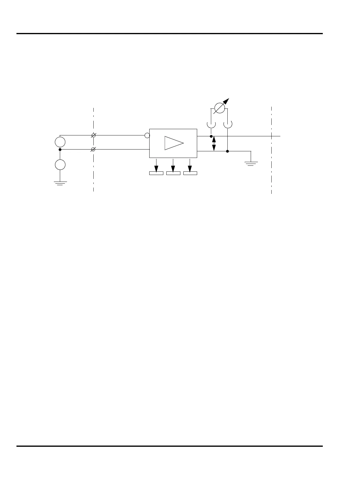
front. The input voltage is measured at the test terminal X3. Make connections as shown in
Figure 5-21. Disconnect the process signal at the connection unit before the connections are
made.
Adjustment of Zero Points, Channel by Channel
The zero points are adjusted, channel by channel, with G1=0.000 V, connected between the
input terminals X+ and X-, on the connection unit and with G2=0:
Adjust the signal U to 0.000 V with the channel potentiometer Z.
CMRR Adjustment, Channel by Channel
With G1 short-circuited and G2=+100 V: Adjust the signal U to 0.000 V with the channel
potentiometer B. With the same connections, change G2 to -100 V and check that the signal
U=0.000 V.
Full Scale Adjustment, Channel by Channel
With G1=Full scale value (FS; usually +10000 mV for voltage input and 20.000 mA over
250 ohm shunt resistor for current input), connected between the input terminals X+ and X- on
the connection unit, and with G2=0. Adjust the output signal U with the channel potentiometer
G to +10000 mV for voltage signal and +5000 mV for current signal.
Change, with the same connections G1 to -10000 mV (-20.000 mA) and check that the output
signal =-10000 mV (-5000 mV).
Figure 5-21. Connections for Channel by Channel Adjustment of DSAI 130
X+
X-
G1
G2
CMV
U
DVM
Connection
unit
ZB
G
Circuit board
OV
X3 connector
at the front

 Loading...