Advant
®
Controller 450 User’s Guide
Chapter 5 Maintenance
5-16 3BSE 002 415R701 Rev A
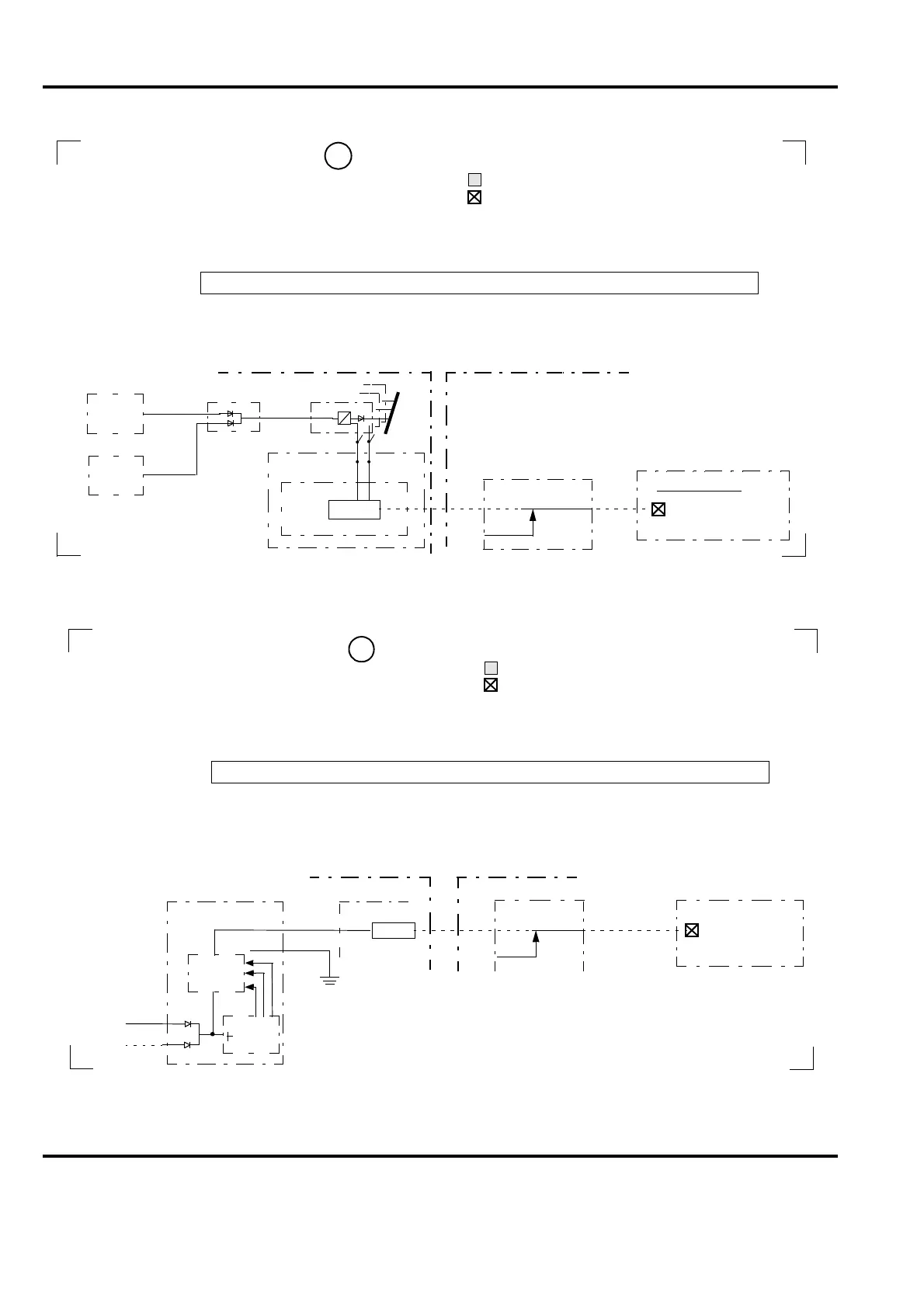
Reference in Advant Controller 400 Display:
Presentation:
Function:
Actions at fault:
Block Diagram:
(I/O) Reg. redundancy
green Normal - all regulators present and OK
red cr Fault - any regulator missing or erroneous
Supervision of redundant 5V regulators in one or several I/O subrack (collecting alarm)
Plain System Message
at fault:
11
Software
DB; AC450
System status OS
Reg. redundancy
Hardware
I/OREG_ERR
Y/N
I/OREG
DIAGN.
DSSR 170
DSBB 172B
24VA
24VB
24 V distribution
2
1
5 V
I/O Power Supply
3
DSSS 171
DSBC 174/176
REGFAIL
REGMISS
POW SUPP ST
I/O voltage regulator faulty Net xx Nod yy
See Section 5.4.9.5, Check of Power Supply
Reference in Advant Controller 400 Display:
Presentation:
Function:
Actions at fault:
Block Diagram:
Controller fan
green Normal
red cr Fault - all or any of three fans erroneous
Supervision of the fan unit in the controller subrack. Note! The Fan Unit requires 24V dc
1. Check function in cabinet
Plain System Message
at fault:
Fan Unit
TC520
Software
DB; AC450
System status OS
Controller fan
Fault ⇒ 24 V
0V
12
2. Check fuses in the fan unit RC527
3. Check electrical signal
Hardware
FAN_ERR
FN
Y/N
FAN
DIAGN.
4. Replace fan unit
X3
1
2
Fan for CPU faulty Net xx Nod yy
(24VA and/or 24VB) for reporting FAN ERR (active fault signal)
Superv.
Fan 1-3
24VA
24VB
 Loading...


