Advant
®
Controller 450 User’s Guide
Chapter 2 Installation
2-74 3BSE 002 415R701 Rev A
Input Signals
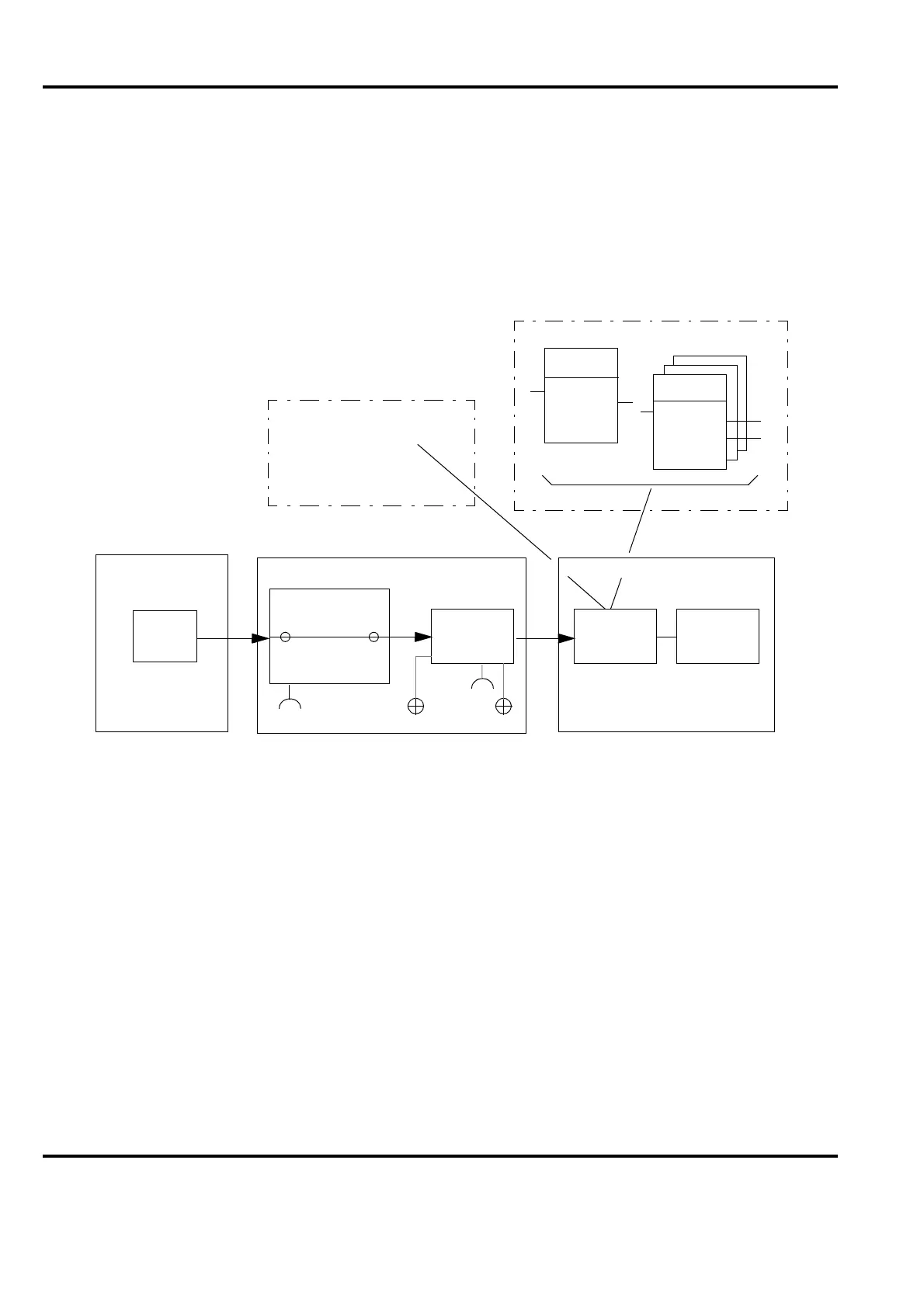
Figure 2-28 shows in principle where to check an input signal in an S100 I/O application.
DI boards provide X90 connector and DI channel LEDs.
AI boards provide X90 connector, a test terminal X3 and a common-to-all-channels A/D
conversion indicating LED.
See separate documentation for detailed information.
• Digital Input Signals
Figure 2-28 shows where you can check a digital input signal in an input channel.
Proceed as follows:
– Use the command MDB (Modify Data Base) to present the data base element.
Use GETAB as an alternative.
– Ensure that the connections of the data base element are filled in correctly for the
signal to be examined. See the data sheet for the data base element.
– Simulate the digital input signal as close to the process transducer as possible or
activate the transducer itself.
– Check that the corresponding yellow LED on the input board concerned illuminates
Figure 2-28. Principal Block Diagram of S100 I/O Input Channel, Test Points
Process
S100 I/O hw interface AC 450 sw interface
Connection
unit
Input
board
Process
object
Data base PC program
DI ch.
AI
(A/D)
X3
X90
Board
Signal
Engineering station
DB elements
VALUE
ERR
NAME
TYPE
ERR
Operator station
- Object display
- Trend curve
 Loading...


