$GYDQW
&RQWUROOHU8VHU¶V*XLGH
6HFWLRQ +HDW'LVVLSDWLRQ
3BSE 002 415R701 Rev A 3-33
&DELQHWVLQ*URXSV
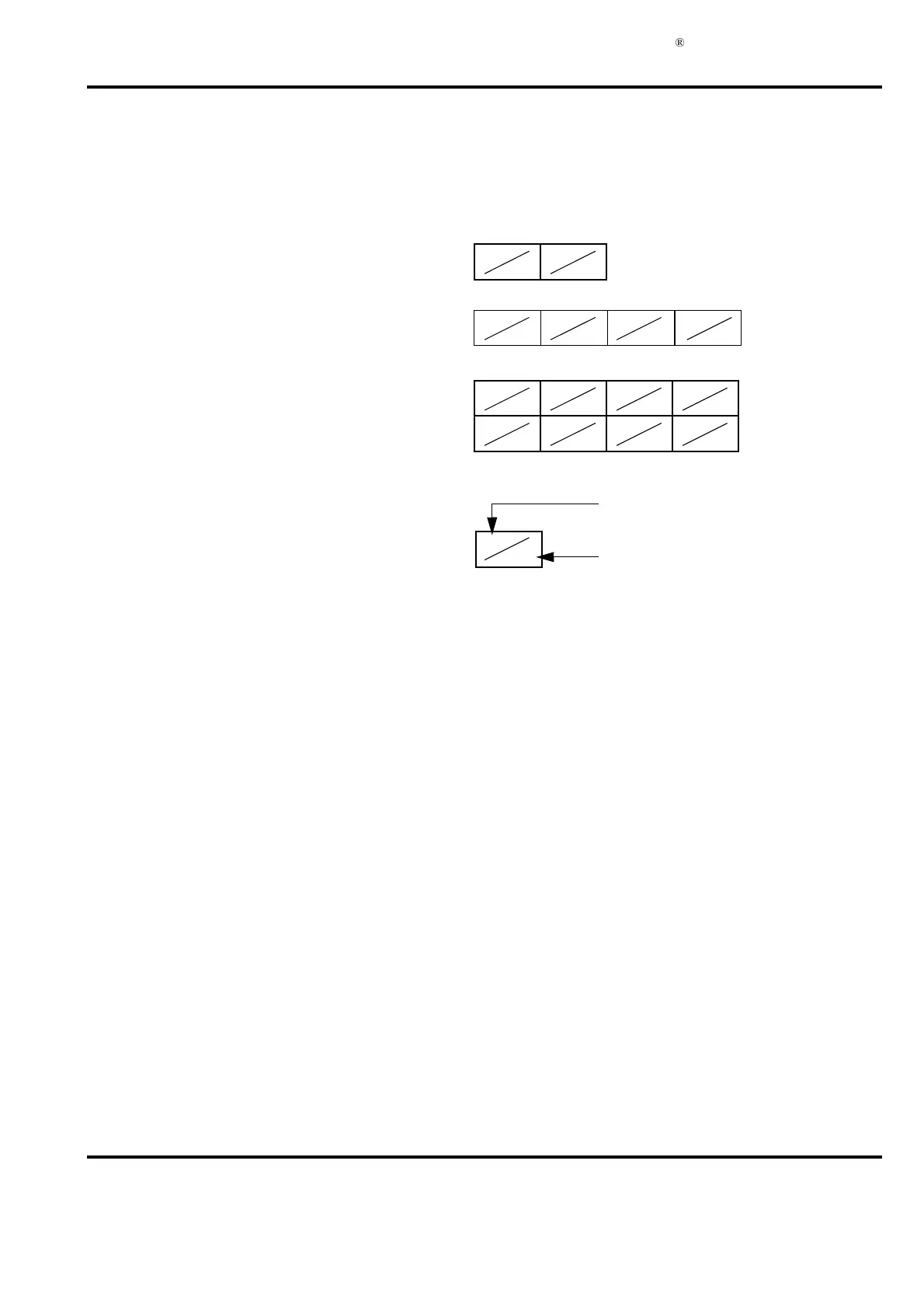
When cabinets are installed in groups, reduce the permitted power dissipation in accordance
with Figure 3-6. The permitted power dissipation in a particular cabinet is the power specified
in Appendix B, RM500 Cabinet - Data Sheet multiplied by a factor from Figure 3-6.
&DOFXODWLRQRI+HDW*HQHUDWHGLQD&DELQHW
When you are calculating the heat generated in a cabinet, add up the heat generated by the
different circuit boards. To this sum, add the heat generated by the power supply units and other
equipment such as an extra modem, extra unit for supply of power to transmitters and so on.
See Appendix E, Current Consumption and Heat Dissipation for the power dissipated as heat by
hardware modules in Advant Controller 450 and the available I/O system. It is assumed that
70% of the channels of an I/O board are active simultaneously.
A power supply unit located beneath the subracks contributes to the total power dissipation with
100 W. Do not include redundant power supply units in the calculation of number of units
because of the load shedding.
The total power dissipated in the cabinet can be written as follows:
)LJXUH 5HGXFWLRQ)DFWRUVIRU&DELQHWV,QVWDOOHGLQ*URXSV
0.95
0.9
0.95
0.9
0.95
0.9
0.9
0.8
0.9
0.8
0.95
0.9
0.9
0.85
0.85
0.75
0.85
0.75
0.9
0.85
0.9
0.85
0.85
0.75
0.85
0.75
0.9
0.85
0.95
0.9
Reduction factor for ventilated
cabinet and tropicalized cabinet
Reduction factor for
sealed cabinet
&DELQHWV
&DELQHWV
&DELQHWV
P
Total
P
C module–
∑
()P
IO board–
∑
()P
Voltagesupplyunit
∑
()P
Sundry
∑
()++ +=
 Loading...


