Advant
®
Controller 450 User’s Guide
Section 5.5.2 Diagnostics and Fault Announcement
3BSE 002 415R701 Rev A 5-9
5.5.2.1 System Status and Plain Language System Messages
You need the following information to make use of the system status displays in a central
operator station when fault finding. The disposition is based on the displays. References for a
listed item to the controller data base and presumed faulty unit or further fault finding
instructions are given then. A reference should be seen as a “short cut” information for the
authorized maintenance personnel. The general safety regulations and principles for fault
finding and user repair must be fully clear before work starts.
Advant Controller 400
The appearance in an Advant Station 500 Series operator station is shown. The lay-out of the
display is not identical in an MasterView 800/1 application. However the information can be
applied.
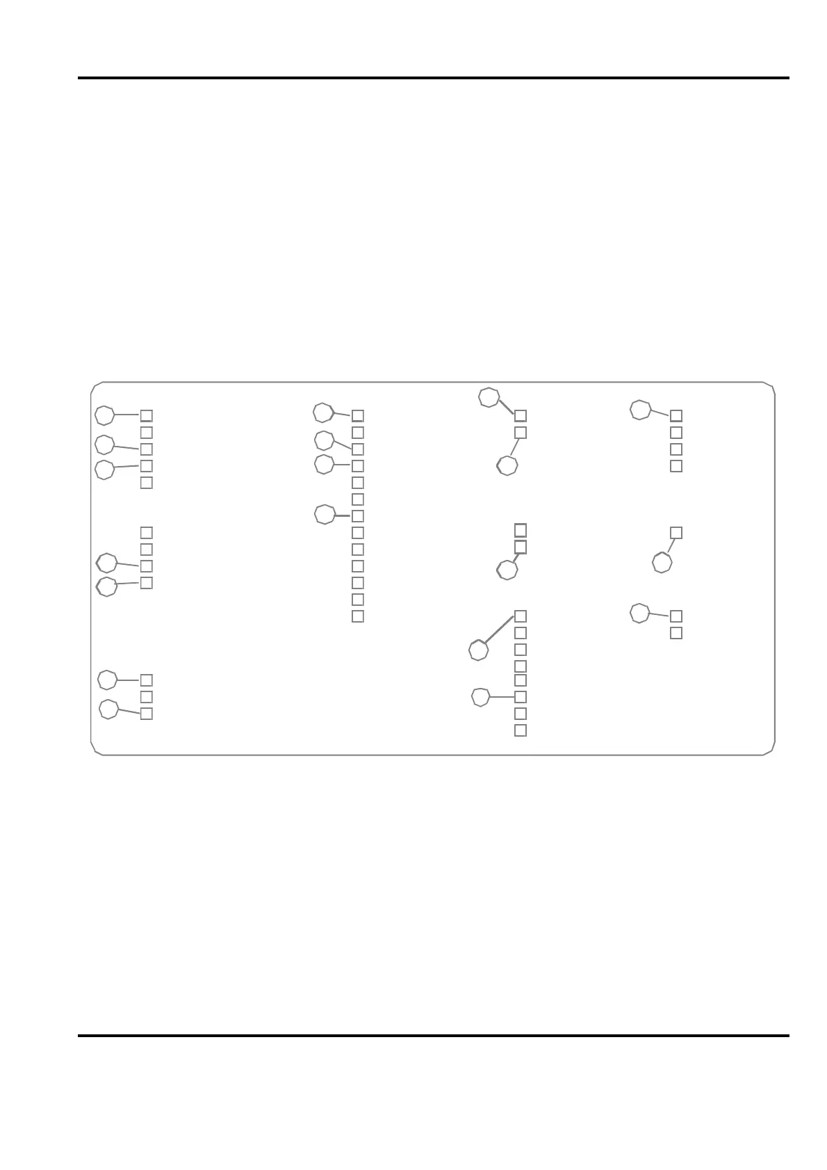
Figure 5-2. System Status Display Advant Controller 400 applied to Advant Controller 450
Controller Power Supply Controller Subrack Fan Terminal
24 V supply A Processor module L Controller fan Terminal 1
24 V supply B Processor module R I/O fan Terminal 2
Reg. redundancy Program card 1.1 Terminal 3
Regulator 1 Program card 3.1 Terminal 4
Regulator 2 Program card 3.2
Program card 4.1
Free pgm module 1
Printer
Batt. volt. 1 Free pgm module 2 Printer 1
Backup Pow. Supp. 1 Free pgm module 3
Batt. volt. 2 Free pgm module 4
Backup Pow. Supp. 2 Free pgm module 5
Additional
Free pgm module 6
External Comm.
Free pgm module 7 F1 EXCom. 1
F2 EXCom. 2
F3
I/O Power Supply
F4
24 V supply A PCF1
24 V supply B PCF2
Reg. Redundancy PCF3
PCF4
1
2
3
4
5
6
7
9
12
17
10
11
8
13
18
19
15
16
S100 I/O Bus Extension
Bus Extension L
Bus Extension R
14
 Loading...


