Home
Fujitsu
Server
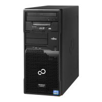
PRIMERGY TX100 S3
Fujitsu PRIMERGY TX100 S3 Maintenance Manual
4
of 1
of 1 rating
348 pages
Give review
Manual
Specs
To Next Page
To Next Page
To Previous Page
To Previous Page
Loading...
TX100 S3
Upgrade and Maintenance Manual
151
Expansion cards and backu
p units
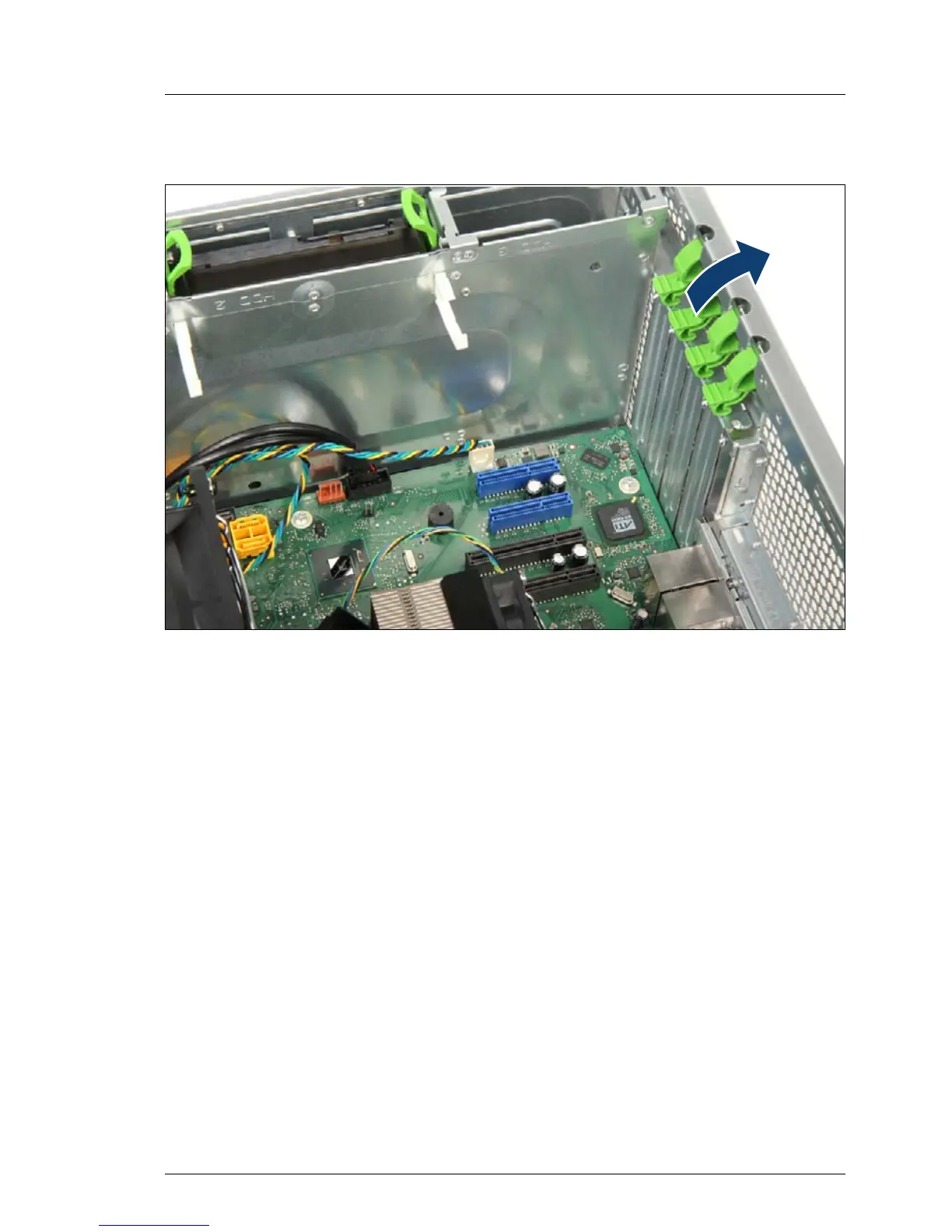
9.2.1.3
Removing
PCI slot bracket
Figure 78: Removing the PCI slot bracket (A)
Ê
Press slightly on the upper end and swing outwards.
Ê
Open the slot bracket clamp.
150
152
Table of Contents
Default Chapter
2
Copyright and Trademarks
2
Table of Contents
5
1 Introduction
17
Where to Find Which Information
19
Notational Conventions
20
2 Before You Start
21
Classification of Procedures
22
Customer Replaceable Units (CRU)
22
Upgrade and Repair Units (URU)
23
Field Replaceable Units (FRU)
24
Average Task Duration
25
Tools You Need at Hand
26
Documents You Need at Hand
27
3 Important Information
29
Safety Instructions
29
Energy Star
36
CE Conformity
36
FCC Class a Compliance Statement
37
Environmental Protection
38
4 Basic Hardware Procedures
41
Using Diagnostics Information
41
Locating the Defective Component
41
Shutting down the Server
42
Disconnecting Power Cord
43
Opening the Server
44
Removing the Side Cover
45
Removing Accessible Drives
47
Removing the Optical Disk Drive (ODD)
47
Removing the Backup Drive
49
Removing the Front Cover
51
Closing the Server
52
Installing the Front Cover
53
Installing the Optical Disk Drive (ODD)
54
Installing the Backup Drive
56
Installing the Side Cover
58
Connecting the Server to the Mains
59
Switching on the Server
60
Removing the HDD Cage
61
Preliminary Steps
61
Installing the HDD Cage
63
Concluding Steps
66
Concluding Software Tasks
67
5 Basic Software Procedures
69
Starting the Maintenance Task
69
Disabling Bitlocker Functionality
69
Removing Backup and Optical Disk Media
70
Verifying and Configuring the Backup Software Solution
71
Note on Server Maintenance in a Multipath I/O Environment
71
Completing the Maintenance Task
73
Updating the System Board BIOS
73
Updating RAID Controller Firmware
75
Enabling Option ROM Scan
76
Verifying and Configuring the Backup Software Solution
77
Enabling Replaced Components in the System BIOS
78
Verifying the System Time Settings
78
Viewing and Clearing the System Event Log (SEL)
79
Viewing the SEL
79
Updating the NIC Configuration File in a Linux Environment
80
Enabling Bitlocker Functionality
82
Performing a RAID Array Rebuild
83
Looking up Changed MAC / WWN Addresses
83
Looking up MAC Addresses
83
Using the Chassis ID Prom Tool
84
Configuring LAN Teaming
84
After Replacing / Upgrading LAN Controllers
85
After Replacing the System Board
85
6 Power Supply
87
Replacing the Standard Power Supply Unit
88
Required Tools
88
Preliminary Steps
88
Disconnecting Power Cables
89
Removing the Power Supply Unit
90
Installing the Power Supply Unit
92
Reconnecting Power Cables
94
Concluding Steps
94
Replacing the 0-Watt Power Supply Unit
95
Required Tools
95
Preliminary Steps
95
Disconnecting Power Cables
96
Removing the Power Supply Unit
98
Installing the Power Supply Unit
100
Reconnecting Power Cables
102
Concluding Steps
103
7 Hard Disk Drives
105
Mounting Order for 3.5-Inch Hdds
106
Installing 3.5-Inch Hdds
107
Required Tools
107
Preliminary Steps
107
Installing a 3.5-Inch HDD
108
Connecting Power
112
SATA Cabling to Onboard Controller
113
SATA Cabling to SATA RAID Controller
116
Concluding Steps
117
Removing 3.5-Inch Hdds
118
Required Tools
118
Preliminary Steps
118
Removing a 3.5-Inch HDD
119
Concluding Steps
123
Replacing a 3.5-Inch HDD
124
Required Tools
124
Preliminary Steps
124
Removing a 3.5-Inch HDD
125
Installing a 3.5-Inch HDD
125
Concluding Steps
125
8 System Fan Modules
127
Basic Information
128
Replacing the System Fan Module 1
130
Required Tools
130
Preliminary Steps
130
Removing the System Fan Module 1
131
Installing the System Fan Module 1
134
Concluding Steps
137
Replacing the System Fan Module 2
138
Required Tools
138
Preliminary Steps
138
Removing the System Fan Module 2
139
Installing the System Fan Module 2
143
Concluding Steps
145
9 Expansion Cards and Backup Units
147
Basic Information
148
Expansion Cards
150
Installing Expansion Cards
150
Required Tools
150
Preliminary Steps
150
Removing PCI Slot Bracket
151
Installing an Expansion Card
153
Connecting Cables to the Expansion Card
154
Connecting a Battery Backup Unit to the Expansion Card
154
Concluding Steps
155
Removing Expansion Cards
156
Required Tools
156
Preliminary Steps
156
Removing an Expansion Card
157
Installing a PCI Slot Bracket
159
Concluding Steps
160
Replacing Expansion Cards
161
Required Tools
161
Preliminary Steps
161
Removing an Expansion Card
162
Installing an Expansion Card
162
Connecting Cables to the Expansion Card
162
Connecting a Battery Backup Unit to the Expansion Card
162
Concluding Steps
162
Replacing TFM
164
Required Tools
164
Preliminary Steps
164
Removing the Defective TFM
164
Installing the New TFM
165
Concluding Steps
165
Backup Units (BBU/FBU)
166
Installing a BBU
166
Required Tools
166
Preliminary Steps
166
Preparing the BBU
167
Installing the BBU Holder into the Chassis
169
Concluding Steps
172
Installing an FBU
173
Required Tools
173
Preliminary Steps
173
Installing TFM to the RAID Controller (if Applicable)
174
Preparing the FBU
175
Installing the FBU Holder into the Chassis
177
Connecting the FBU Adapter Cable to the TFM
178
Concluding Steps
178
Removing a BBU
179
Required Tools
179
Preliminary Steps
179
Removing the BBU Holder from the Chassis
180
Concluding Steps
181
Removing an FBU
182
Required Tools
182
Preliminary Steps
182
Disconnecting the FBU Adapter Cable from the TFM
183
Removing the FBU Holder from the Chassis
183
Concluding Steps
183
Replacing a BBU
184
Required Tools
184
Preliminary Steps
184
Removing a BBU from the Chassis
184
Removing the BBU from the BBU Holder
185
Installing a New BBU
185
Concluding Steps
186
Replacing an FBU
187
Required Tools
187
Preliminary Steps
187
Removing the FBU from the Chassis
187
Removing the FBU from the FBU Holder
188
Installing a Replacement FBU
189
Concluding Steps
189
Additional Tasks
190
Mounting Expansion Card Slot Brackets
190
Required Tools
190
General Instructions
191
10 Main Memory
201
Basic Information
202
Memory Sequence
202
Operation Modes
203
Installing Memory Modules
204
Required Tools
204
Preliminary Steps
204
Installing a Memory Module
205
Concluding Steps
206
Removing Memory Modules
207
Required Tools
207
Preliminary Steps
207
Removing a Memory Module
208
Concluding Steps
208
Replacing Memory Modules
209
Required Tools
209
Preliminary Steps
209
Removing a Memory Module
210
Installing a Memory Module
210
Concluding Steps
210
11 Processor
211
Basic Information
212
Upgrading or Replacing the Processor
212
Required Tools
212
Preliminary Steps
212
Removing the Processor Heat Sink
213
Removing the Processor Heat Sink Type a
213
Removing the Processor Heat Sink Type B
215
Removing the Processor
217
Installing the Processor
220
Applying Thermal Paste
224
Installing the Processor Heat Sink
226
Installing the Processor Heat Sink Type a
228
Installing the Processor Heat Sink Type B
230
Concluding Steps
232
Replacing the Processor Heat Sink
232
Required Tools
232
Preliminary Steps
233
Removing the Processor Heat Sink
233
Applying Thermal Paste
233
Installing the Processor Heat Sink
233
Concluding Steps
233
12 Accessible Drives
235
Basic Information
236
Installing Accessible Drives
237
Required Tools
237
Preliminary Steps
237
Removing the Accessible Drive Dummy Cover of Bay 2
238
Installing an Optical Disk Drive (ODD)
240
Preparing the Optical Disk Drive
240
Installing the Optical Disk Drive
242
Installing a Slimline Optical Disk Drive (ODD)
245
Mounting the Slimline Drive in the Slide-In Unit
245
Preparing the Slide-In Unit
246
Installing the Slide-In Unit
249
Installing a Backup Drive
252
Preparing the Backup Drive
252
Installing the Backup Drive
254
Concluding Steps
256
Removing Accessible Drives
257
Required Tools
257
Preliminary Steps
257
Removing an Optical Disk Drive (ODD)
258
Removing a Slimline Optical Disk Drive (ODD)
260
Removing a Backup Drive
262
Installing Accessible Drive Dummy Cover
264
Installing the Dummy Cover in Bay 2
264
Installing the Cover in Bay 2
265
Concluding Steps
265
Replacing Accessible Drives
266
Required Tools
266
Preliminary Steps
266
Replacing an Optical Disk Drive (ODD)
267
Replacing a Slimline Optical Disk Drive (ODD)
268
Replacing a Backup Drive
270
Concluding Steps
271
13 Front Panel and External Connectors
273
Replacing the Front Panel Module
273
Required Tools
273
Preliminary Steps
274
Removing the On/Off Button
275
Removing the HDD Activity LED
275
Removing the Front Panel Cable
276
Installing the Front Panel Cable
277
Installing the On/Off Button and the HDD Activity LED
278
Concluding Steps
279
Replacing the Front USB Module
280
Required Tools
280
Preliminary Steps
280
Disconnecting the Front USB Cable
281
Removing the Defective Front USB Module
282
Removing the Defective Front USB Board
283
Installing the New Front USB Board
284
Installing the New Front USB Module
286
Installing the Front USB Cable
287
Concluding Steps
287
14 System Board and Components
289
Replacing the CMOS Battery
289
Required Tools
290
Preliminary Steps
290
Replacing the Defective CMOS Battery
291
Concluding Steps
292
Trusted Platform Module (TPM)
293
Installing the TPM
293
Required Tools
293
Preliminary Steps
293
Installing the TPM
294
Concluding Steps
296
Removing the TPM
297
Required Tools
298
Preliminary Steps
298
Removing the TPM
299
Concluding Steps
301
Replacing the TPM
302
Required Tools
302
Preliminary Steps
303
Removing the TPM
303
Re-Installing the TPM
303
Concluding Steps
303
Replacing the System Board
304
Required Tools
305
Preliminary Steps
306
Removing the System Board
306
Installing the System Board
310
Mounting the System Board
310
Swapping the Processor
313
Concluding Steps
318
15 Cabling
321
Cabling Overview
322
Cable Plans
323
Fan Cabling
328
Replacing the Power Cable
329
Required Tools
330
Preliminary Steps
330
Disconnecting/Connecting the Power Cable
330
Concluding Steps
334
Replacing the Front USB Cable
334
Required Tools
334
Preliminary Steps
334
Disconnecting/Connecting the Front USB Cable
335
Concluding Steps
336
Storing Not Used SATA Cables
336
16 Appendix
337
Mechanical Overview
337
Server Front
337
Server Rear
338
Server Interior
339
Configuration Tables
340
Hard Disk Drives Mounting Order
340
Memory Board Configuration Table
340
Expansion Card Configuration Table
340
Connectors and Indicators
341
Connectors on the System Board
341
Onboard Connectors
341
Onboard Settings
343
I/O Panel Connectors
344
I/O Panel Indicators
345
Connectors and Indicators on the Front Panel
346
Front Panel Connectors and Indicators
346
Minimum Startup Configuration
347
Other manuals for Fujitsu PRIMERGY TX100 S3
Operating Manual
72 pages
4
Based on 1 rating
Ask a question
Give review
Questions and Answers:
Need help?
Do you have a question about the Fujitsu PRIMERGY TX100 S3 and is the answer not in the manual?
Ask a question
Fujitsu PRIMERGY TX100 S3 Specifications
General
Brand
Fujitsu
Model
PRIMERGY TX100 S3
Category
Server
Language
English
Related product manuals
Fujitsu PRIMERGY TX100 S1
46 pages
Fujitsu PRIMERGY TX100 S2
66 pages
PRIMERGY TX100 S3 Core Edition
90 pages
Fujitsu PRIMERGY TX150 S3
95 pages
Fujitsu PRIMERGY TX120 S3
82 pages
Fujitsu Primergy RX300 S3
313 pages
Fujitsu Primergy RX100 S3
287 pages
Fujitsu PRIMERGY RX200 S3
100 pages
Fujitsu PRIMERGY TX150 S4
97 pages
Fujitsu PRIMERGY TX1330 M1
86 pages
Fujitsu PRIMERGY TX1320 M1
86 pages
Fujitsu PRIMERGY TX1330 M2
86 pages
 Loading...