Models 2500 and 2502 User’s Manual Range, Digits, Speed, and Filters 6-7
Remote speed programming
Speed commands
Table 6-4 summarizes commands to control speed. Although commands for both channel
1 and channel 2 are included, the NPLC setting is global and affects both channels. See
Section 17 for more information.
Speed programming example
Send the following command to set the speed for both channel 1 and channel 2 to 10 PLC:
:SENS1:CURR:NPLC 10
Filters
Filtering stabilizes noisy measurements caused by noisy input signals. However, the more
filtering that is used, the slower the measurement process becomes. The Model 2500 uses
two stages of filtering: average and median. The displayed, stored, or transmitted reading
is simply the result of the filtering processes.
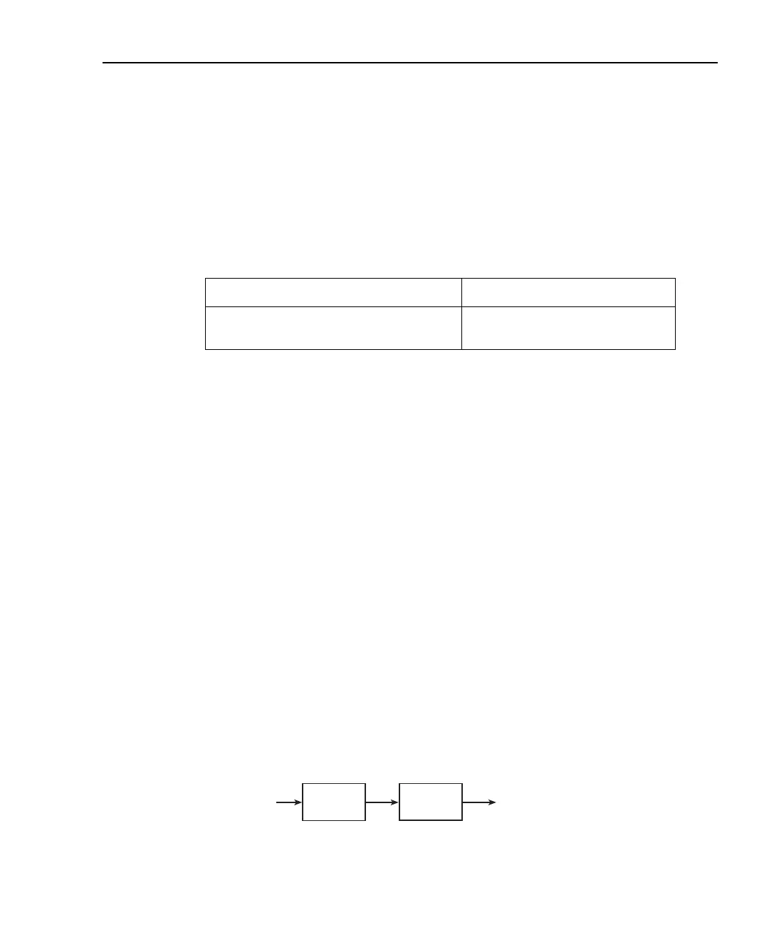
Filter stages
The Model 2500 uses a 2-stage filtering system as shown in Figure 6-2. The first stage
applies the Average Filter (Moving or Repeat) to the measurement conversions. The sec-
ond stage applies the Median Filter to the output of the first stage. When a filter stage is
disabled, a reading simply passes through it.
Figure 6-2
2-stage filtering
Table 6-4
Speed commands
Command Description
:SENSe[1]:CURRent:NPLCycles <n>
:SENSe2:CURRent:NPLCycles <n>
Set speed (n = PLC, 0.01 to 10).
Set speed (n = PLC, 0.01 to 10).
A/D
Conversions
Average*
Filter
Median
Filter
Final
Filtered
Readings
*Repeat or Moving
Test Equipment Depot - 800.517.8431 - 99 Washington Street Melrose, MA 02176
TestEquipmentDepot.com

 Loading...


