4-2 Photodiode Measurements Models 2500 and 2502 User’s Manual
Configuring measurements
Measurement configuration menu
Press CONFIG then MSR1 or MSR2 to access channel 1 or channel 2 configuration menu
shown in Table 4-1. In Section 1 use the “Rules to navigate menus” to select the various
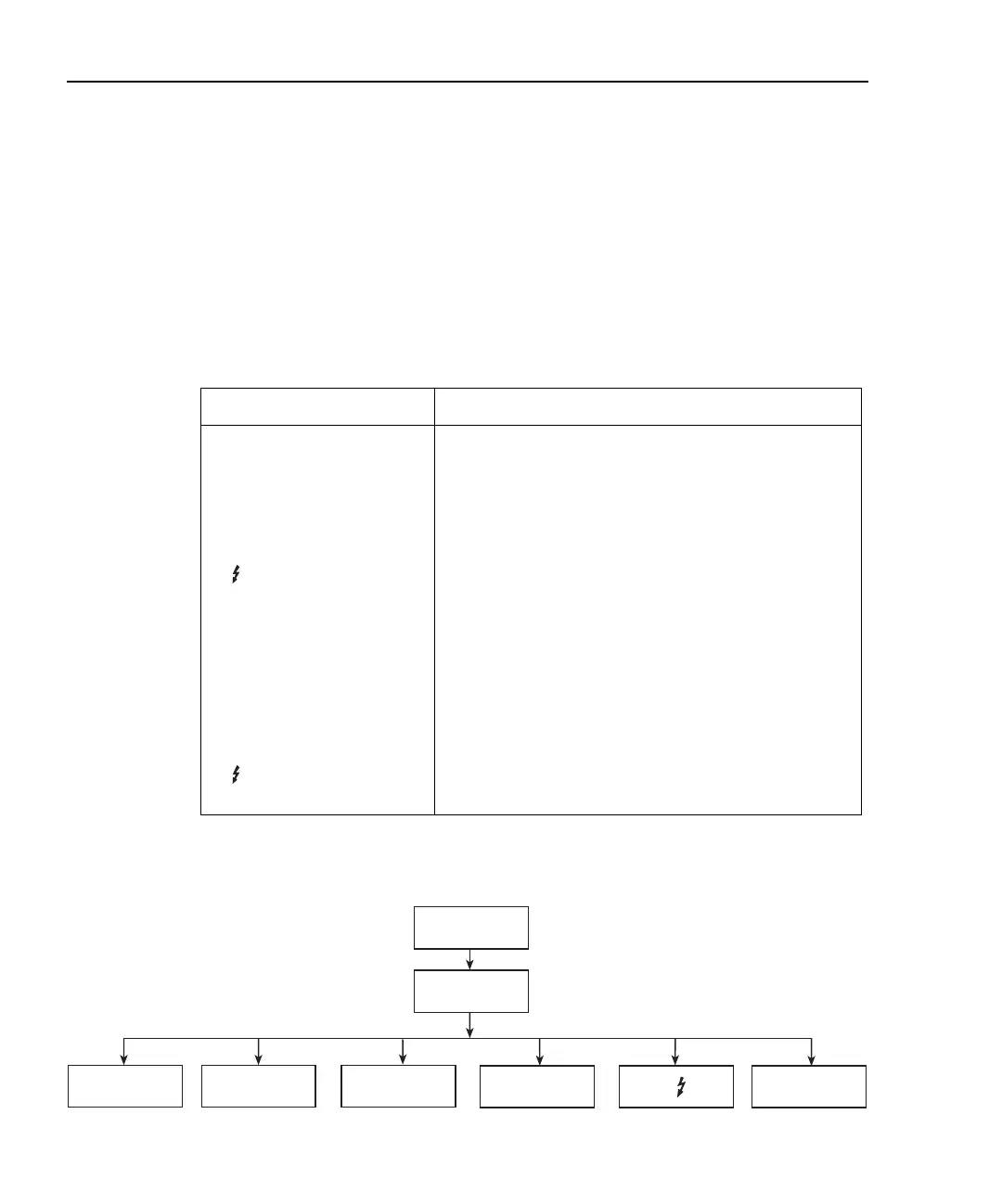
items in the menu tree, which is shown in Figure 4-1.
Figure 4-1
Measurement configuration menu tree
Table 4-1
MSR1 and MSR2 configuration menus
Configuration menu item Description
CONFIG MSR1
CONFIG MSR1 BUTTON
I
I/V
V/I
MX + B_UNIT
P
P→
CONFIG MSR2
CONFIG MSR2 BUTTON
I
I/V
V/I
MX + B_UNIT
P
P→
Configure channel 1 measurement.
Current measurement.
I/V measurement (conductance).
V/I measurement (resistance).
MX + B measurement.
Electrical power measurement (V X I).
Optical power [(I
measured
– I
dark current
)/Responsivity].
Configure channel 2 measurement.
Current measurement.
I/V measurement (conductance).
V/I measurement (resistance).
MX + B measurement.
Electrical power measurement (V X I).
Optical power [(I
measured
– I
dark current
)/Responsivity].
Config
I
I/V
V/I
MSR1/MSR2
MX+B
P P→
Test Equipment Depot - 800.517.8431 - 99 Washington Street Melrose, MA 02176
TestEquipmentDepot.com

 Loading...


