12-2 Digital I/O Port, Output Enable, and Output Configuration Models 2500 and 2502 User’s Manual
Digital I/O port
The Model 2500 has a digital input/output port that can be used to control external digital
circuitry, such as a handler that is used to perform binning operations when testing limits.
Port configuration
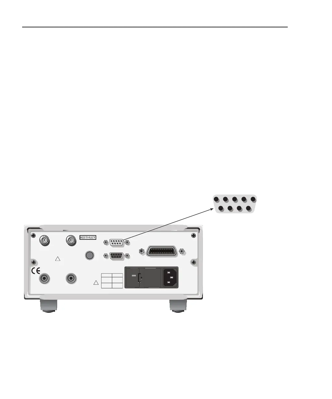
The digital I/O port is located on the rear panel and is shown in Figure 12-1. Note that a
standard male DB-9 connector is used for the digital I/O port.
NOTE The four digital output lines and the SOT line are primarily intended for limit
testing with a device handler. See Section 11, “Limit Testing,” for details on per-
forming limit tests and interfacing to handlers and Section 10, “Triggering,” for
information on programming the Model 2500 to respond to the start-of-test
(SOT) pulse from a handler.
Figure 12-1
Output Enable and digital I/O
120
LINE RATING
50, 60Hz
60 VA MAX
FUSE LINE
630 mAT
(SB)
315 mAT
(SB)
100 VAC
120 VAC
220 VAC
240 VAC
1 = Digital Output #1
2 = Digital Output #2
3 = Digital Output #3
4 = Digital Output #4
(EOT, /EOT, BUSY, /BUSY)
5 = Ground
6 = Trigger Input (SOT)
7 = +5V
8 = Output Enable
9 = Ground
Model 2500
1
5
6
9
CAT I
MADE IN
U.S.A.
DIGITAL I/O
RS-232
TRIGGER LINK
INPUT
CHANNEL 1
INPUT
CHANNEL 2
VOLTAGE SOURCE
OUTPUT CHANNEL 1
VOLTAGE SOURCE
OUTPUT CHANNEL 2
RATINGS MAX
100V @ 20mA
COMMON
MODE
200V
RATINGS MAX
100V @ 20mA
!
!
IEEE-488
(CHANGE IEEE ADDRESS
WITH FRONT PANEL MENU)
Test Equipment Depot - 800.517.8431 - 99 Washington Street Melrose, MA 02176
TestEquipmentDepot.com

 Loading...


