12-4 Digital I/O Port, Output Enable, and Output Configuration Models 2500 and 2502 User’s Manual
Digital output configuration
There are two basic methods to connect external components to the digital output lines,
sink operation and source operation.
Sink operation
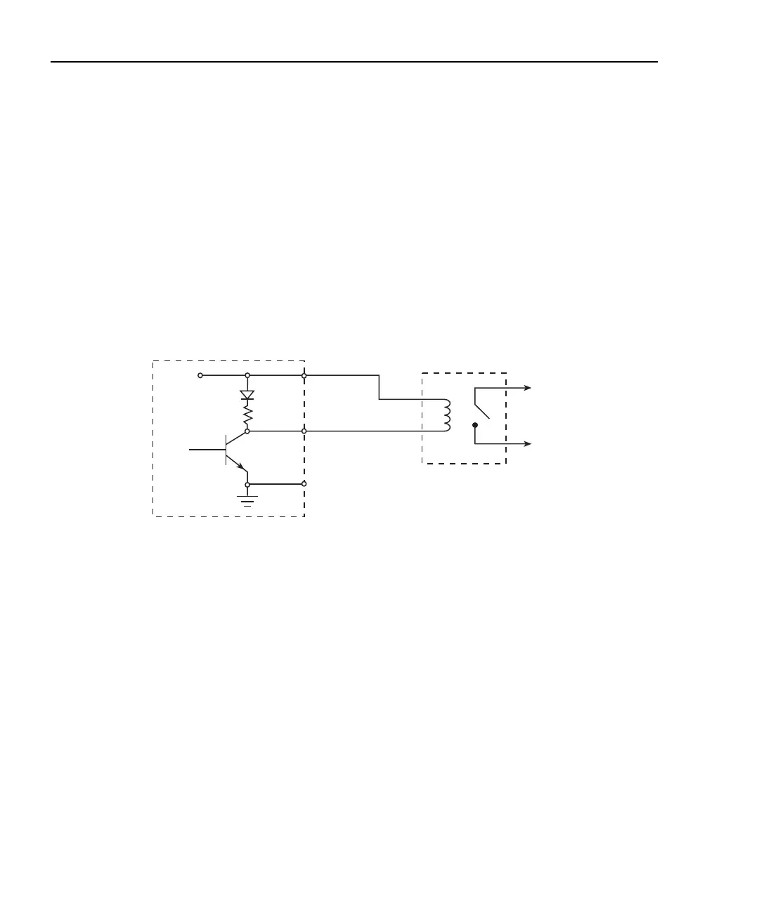
Figure 12-2 shows the basic output configuration for sink operation. Note that the external
relay coil is connected between the digital output line (pins 1 to 4) and +5V (pin 7). With
this configuration, the digital output line must be set LO to energize the relay, and the
maximum sink current is 500mA.
Figure 12-2
Sink operation
Model 2500 External
Relay
To Other
Circuits
+5V
Maximum Sink Current: 500mA
Pin 7
Pins 1-4
Pin 9
Digital I/O
Port
Test Equipment Depot - 800.517.8431 - 99 Washington Street Melrose, MA 02176
TestEquipmentDepot.com

 Loading...


