2-6 Connections Model 2500 and 2502 User’s Manual
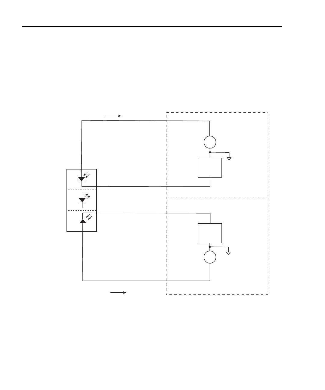
Equivalent circuit
Figure 2-4 shows an equivalent circuit for the connection scheme shown in Figure 2-3.
The circuit includes two ammeters to make current measurements and two voltage sources
to bias the DUTs. Note that channel 1 and channel 2 analog common terminals are floating
and independent of one another.
Figure 2-4
Equivalent circuit of photodiode test connections
Connection considerations
To avoid noise and offset currents that could degrade measurement accuracy, be sure to
use only quality, low-noise triax cables for INPUT connections. Also keep cables and test
fixtures away from vibration and varying temperatures to minimize generated cable cur-
rents. See Appendix F, “Measurement Considerations,” for information on these and other
possible measurement problems and how to avoid them.
Model 2500
Back
Photodiode
Forward
Photodiode
Laser
Diode
V-Source
A
A
INPUT HI
INPUT HI
Channel 1
Channel 2
Channel 1
Analog
Common
Channel 2
Analog
Common
I
I
OUTPUT
OUTPUT
V-Source
Test Equipment Depot - 800.517.8431 - 99 Washington Street Melrose, MA 02176
TestEquipmentDepot.com

 Loading...


