2-14 Connections Model 2500 and 2502 User’s Manual
Equivalent circuits
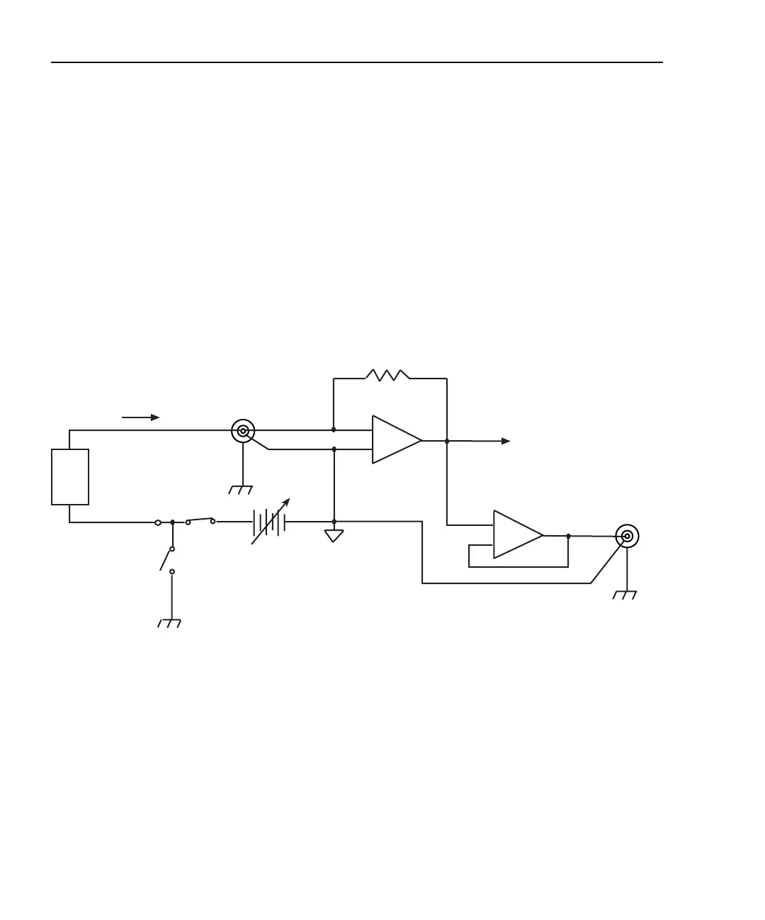
Figure 2-12 shows an equivalent circuit of the analog outputs with the ground connect
mode disabled. (Only one channel is shown; the other channel is identical.) Note that the
analog output circuit consists of a gain/buffer amplifier, and the analog output LO is con-
nected to floating common.
Figure 2-13 shows an equivalent circuit with the ground connect mode enabled. In this
case, since one side of the voltage bias source is connected to chassis ground, analog
output LO can float up to ±100V above chassis ground depending on the voltage bias
source setting.
Figure 2-12
Analog output equivalent circuit with ground connect disabled
-
+
Floating channel 1
or channel 2
common
Feedback
Ammeter
To A/D
Converter
Bias Source
0 to ±10V or
0 to ±100V
20mA Max
VOLTAGE
SOURCE
OUT
Triax
INPUT
20mA Max
Note: One channel shown.
Other channel is identical.
Chassis
Ground
HI
LO
Ground
Connect
Disabled
Chassis
Ground
Output
Enable
R
F
DUT
I
-
+
LO
HI
Buffer
Amplifier
ANALOG
OUT
Chassis
Ground
Test Equipment Depot - 800.517.8431 - 99 Washington Street Melrose, MA 02176
TestEquipmentDepot.com

 Loading...


