) The lifting tools for the engine are designed to t together
with a standard crane hook with a lifting capacity in ac-
cordance with the gure stated in the table. If a larger
crane hook is used, it may not t directly to the overhaul
tools, and the use of an intermediate shackle or similar
between the lifting tool and the crane hook will affect the
requirements for the minimum lifting height in the engine
room (dimension B)
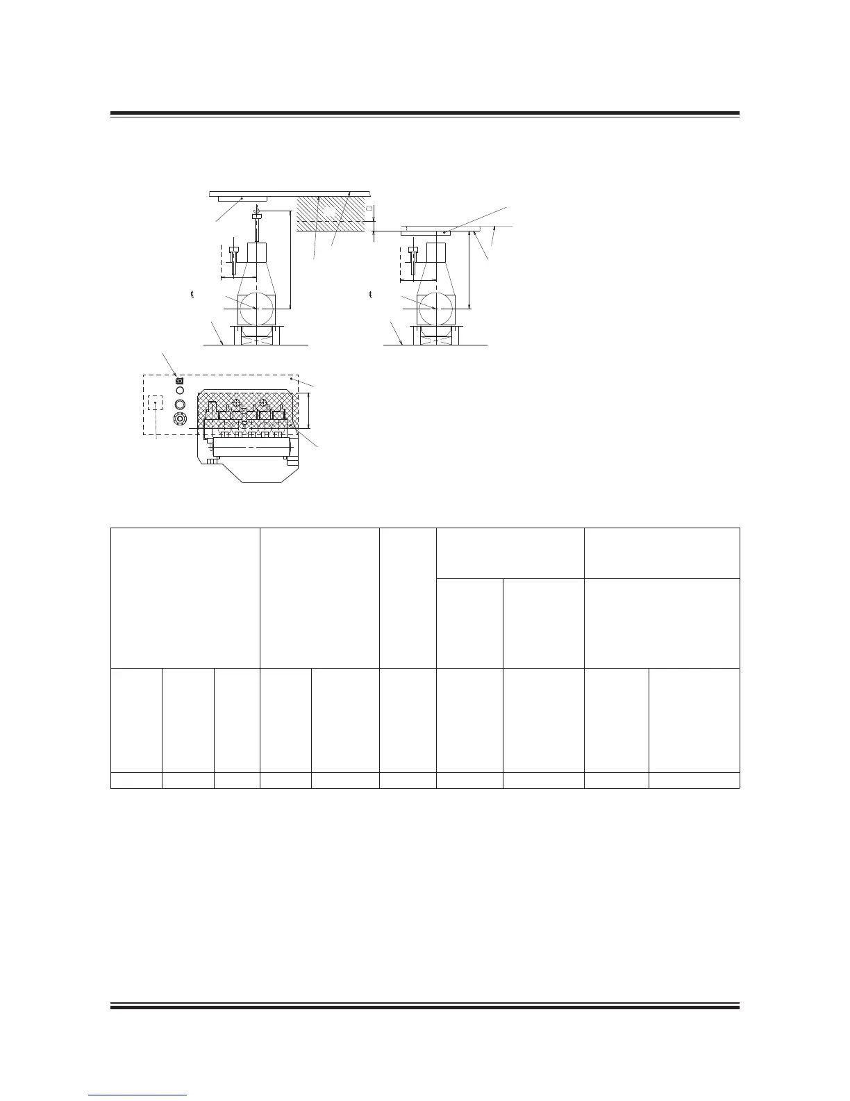
2) The hatched area shows the height where an MAN B&W
DoubleJib Crane has to be used.
079 43 11-5.1.0
The crane hook travelling area must cover at least
the full length of the engine and a width in accord-
ance with dimension A given on the drawing, see
crosshatched area.
It is furthermore recommended that the engine
room crane can be used for transport of heavy
spare parts from the engine room hatch to the
spare part stores and to the engine. See example
on this drawing.
The crane hook should at least be able to reach
down to a level corresponding to the centre line of
the crankshaft.
For overhaul of the turbocharger(s), trolley mount-
ed chain hoists must be installed on a separate
crane beam or, alternatively, in combination with
the engine room crane structure, see ‘Crane beam
for overhaul of turbochargers’ with information
about the required lifting capacity for overhaul of
turbocharger(s).
Fig. 5.04.01: Engine room crane
Engine room crane
Weight in kg
including lifting tools
Crane capacity
in tons selected
in accordance with
DIN and JIS
standard capacities
Crane
operating
width
in mm
Normal crane
Height to crane hook
in mm for:
MAN B&W DoubleJib Crane
Normal
lifting
procedure
Reduced
height lifting
procedure
involving
tilting of main
components
(option)
Buildingin height
in mm
Cylinder
cover
complete
with
exhaust
valve
Cylinder
liner with
cooling
jacket
Piston
with
piston
rod and
stufng
box
Normal
crane
MAN B&W
DoubleJib
Crane
A
Minimum
distance
B
Minimum
height from
centre line
crankshaft
to centre
line crane
hook
B
Minimum
height from
centre line
crankshaft
to underside
deck beam
C
Minimum
height from
centre line
crankshaft
to under-
side deck
beam
D
Additional height
required for
removal of
exhaust valve
without remov-
ing any exhaust
valve stud
550
450 325 0.63 2x0.5 ,350 5,400 - 5,25 275
 Loading...


