MAN B&W 6.04
Page 10 of 12
MAN Diesel
MAN B&W MC/MCC, ME/ME-B/MEC/MEGI-T-II engines 198 71 40-9.0
∆M
amb%
= 0.41 x (T
air
25) + 0.03 x (p
bar
1000) + 0.19 x (T
CW
25 ) 0.011 x (∆p
M
300) % [7]
∆T
amb
= 1.6 x (T
air
25) 0.01 x (p
bar
1000) +0.1 x (T
CW
25) + 0.05 x (∆p
M
300) °C [8]
where the following nomenclature is used:
∆M
amb%
: change in exhaust gas amount, in % of amount at ISO conditions
∆T
amb
: change in exhaust gas temperature, in °C compared with temperatures at ISO conditions
P
S%
= (P
S
/P
M
) x 100%
∆m
S%
= 37 x (P
S
/P
M
)
3
87 x (P
S
/P
M
)
2
+ 31 x (P
S
/P
M
) + 19
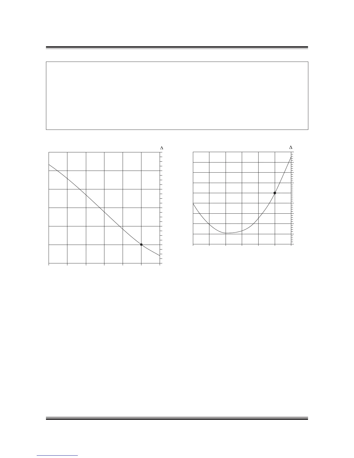
Fig. 6.04.11: Change of specific exhaust gas amount, ∆m
s%
in % at part load, and valid for FPP and CPP
P
S%
= (P
S
/P
M
) x 100%
∆T
S
= 280 x (P
S
/P
M
)
2
410 x (P
S
/P
M
) + 130
Fig. 6.04.12: Change of exhaust gas temperature, ∆T
S
in
°C at part load, and valid for FPP and CPP
178 24 623.0 178 24 635.0
c) Correction for engine load
Figs. 6.04.11 and 6.04.12 may be used, as
guidance, to determine the relative changes
in the specific exhaust gas data when running
at part load, compared to the values in the
specified MCR point, i.e. using as input P
S%
=
(P
S
/P
M
) x 100%:
∆m
s%
: change in specific exhaust gas amount,
in % of specific amount at specified MCR
point, see Fig. 6.04.11.
∆T
s
: change in exhaust gas temperature, in °C,
see Fig. 6.04.12.
16
14
20
18
12
10
8
6
4
4
2
2
0
50 60 70 80 90 100 110
P
S%
Engine load, % specified MCR power
m
S%
M
50 60 70 80 90 100 110
P
S%
Engine load, % specified MCR power
M
20
15
10
5
0
-5
-10
-15
-20
-25
T
S
°C
Fig. 6.04.10: Exhaust gas correction formula for ambient conditions and exhaust gas back pressure
 Loading...


