MAN B&W 15.01
Page 1 of 1
MAN Diesel
MAN B&W S42MC7, S35MC7, L35MC6, S26MC6 198 64 017.1
Exhaust Gas System
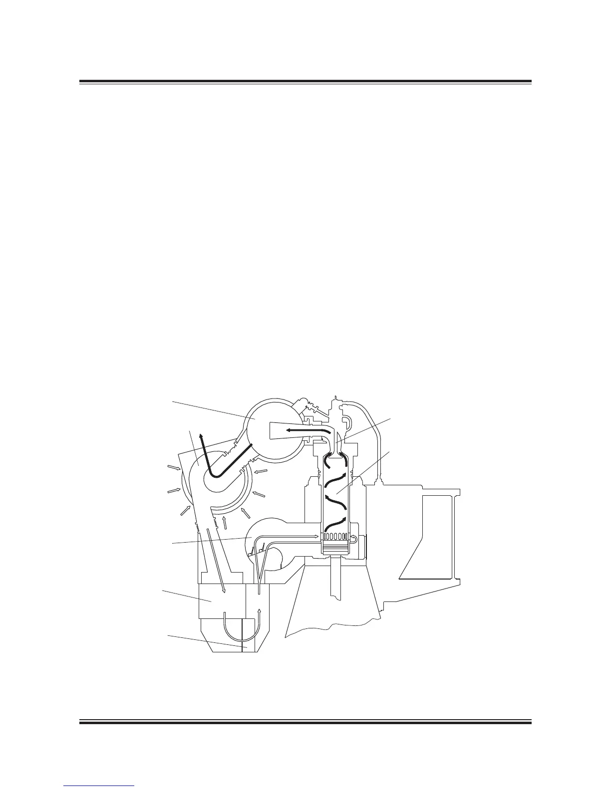
The exhaust gas is led from the cylinders to the
exhaust gas receiver where the fluctuating pres-
sures from the cylinders are equalised and from
where the gas is led further on to the turbocharger
at a constant pressure. See fig. 15.01.01.
Compensators are fitted between the exhaust
valve housings and the exhaust gas receiver and
between the receiver and the turbocharger. A pro-
tective grating is placed between the exhaust gas
receiver and the turbocharger. The turbocharger
is fitted with a pickup for monitoring and remote
indication of the turbocharger speed.
The exhaust gas receiver and the exhaust pipes
are provided with insulation, covered by steel
plating.
Turbocharger arrangement and cleaning systems
The turbocharger is located on the aft end of the
engine. In case of 10-12 cylinders, however, the en-
gine is fitted with two turbochargers located on the
exhaust side.
The engine is designed for the installation of the
MAN Diesel turbocharger types TCA (4 59 101),
ABB turbocharger type A100 (4 59 102), or MHI
turbocharger type MET (4 59 103).
All makes of turbochargers are fitted with an ar-
rangement for soft blast cleaning of the turbine
side, and optionally water washing of the com-
pressor side, option: 4 59 145, see Figs. 15.02.02
and 15.02.03. Washing of the turbine side is only
applicable by special request to TC manufacturer
on MAN Diesel turbochargers.
Exhaust valve
Cylinder liner
Exhaust gas
receiver
Turbocharger
Scavenge air
receiver
Scavenge
air cooler
Water mist
catcher
Fig. 15.01.01: Exhaust gas system on engine
178 07 274.1
 Loading...


