EasyManuals Logo
Home>Man>Engine>B&W L35MC6-TII

Man B&W L35MC6-TII User Manual

Man B&W L35MC6-TII
375 pages
To Next Page IconTo Next Page
To Previous Page IconTo Previous Page
Page #270 background imageLoading...
Page #270 background image
MAN B&W 15.06
Page 3 of 3
MAN Diesel
198 64 13-7.0MAN B&W L35MC6
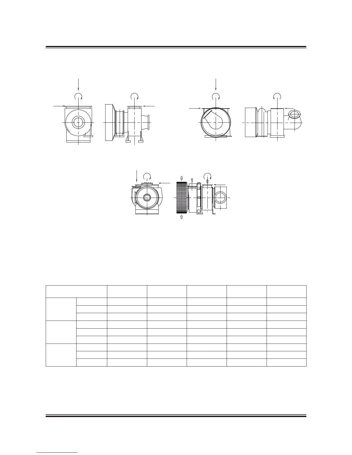
Table 5.06.04 indicates the maximum permis-
sible forces (F, F2 and F3) and moments (M and
M3), on the exhaust gas outlet ange of the turbo-
charger(s). Reference is made to Fig. 5.06.03.
Table 15.06.04: The max. permissible forces and moments on the turbocharger’s gas outlet anges
Turbocharger M1 M3 F1 F2 F3
Make Type Nm Nm N N N
MAN Diesel
TCR22 7,700 3,800 0,200 0,200 5,000
NA34 2,600 ,700 4,300 4,300 ,700
NA40 3,000 2,000 5,000 5,000 2,000
ABB
TPL65 ,00 700 700 ,600 ,00
TPL69 3,700 3,700 7,500 7,000 7,000
TPL73 5,500 5,500 9,500 9,000 9,000
MHI
MET33 2,700 ,400 4,900 ,700 ,600
MET42 3,400 ,700 5,800 2,000 ,800
MET53 4,900 2,500 7,300 2,600 2,300
078 38 48-6.2.0
-
-
&
&&
&
-!.æ$IESEL
-
&
&
-ITSUBISHI
-
- -
&&
&
!""æ40,
Fig. 15.06.03: Forces and moments on the turbochargers’ exhaust gas outlet ange

Table of Contents

Questions and Answers:

Question and Answer IconNeed help?

Do you have a question about the Man B&W L35MC6-TII and is the answer not in the manual?

Man B&W L35MC6-TII Specifications

General IconGeneral
BrandMan
ModelB&W L35MC6-TII
CategoryEngine
LanguageEnglish

Related product manuals