MAN B&W 5.18
Page 3 of 8
MAN Diesel
198 46 953.5MAN B&W S70MC, S70MC-C/ME-C/ME-GI, L70MC-C/ME-C,
S60MC, S60MC-C/ME-C/ME-GI/ME-B, L60MC-C/ME-C,
S50MC, S50MC-C/ME-C/ME-B, S46MC-C/ME-B, S42MC,
S40MC-C/ME-B, S35MC, S35MC-C/ME-B, L35MC, S26MC
Main Dimensions
Symbol Unit Ballast Loaded
Length between perpendiculars LPP m
Length of load water line LWL m
Breadth B m
Draft at forward perpendicular TF m
Draft at aft perpendicular TA m
Displacement o m3
Block coefficient (LPP) CB
Midship coefficient CM
Waterplane area coefficient CWL
Wetted surface with appendages S m2
Centre of buoyancy forward of LPP/2 LCB m
Propeller centre height above baseline H m
Bulb section area at forward perpendicular AB m2
178 22 970.0
Table 5.18.03: Data sheet for propeller design purposes, in case model test is not available this table should be filled in
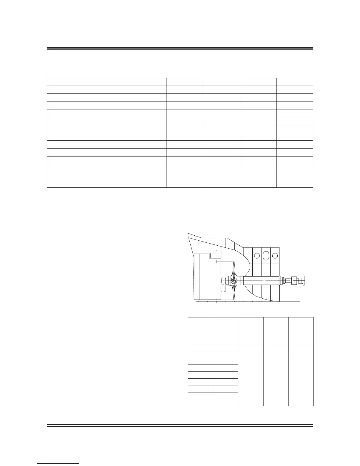
Propeller clearance
To reduce pressure impulses and vibrations emit-
ted from the propeller to the hull, MAN Diesel
recommend a minimum tip clearance as shown in
Fig. 5.18.04.
For ships with slender aft body and favourable
inflow conditions the lower values can be used,
whereas full afterbody and large variations in
wake field cause the upper values to be used.
In twinscrew ships the blade tip may protrude
below the base line.
Hub
Dismant-
ling
of cap
X mm
High skew
propeller
Y mm
Nonskew
propeller
Y mm
Baseline
clearance
Z mm
VBS 1280 390
1520%
of D
2025%
of D
Min.
50100
VBS 1380 420
VBS 1460 450
VBS 1560 480
VBS 1680 515
VBS 1800 555
VBS 1940 590
VBS 2080 635
VBS 2240 680
178 48 589.0
Fig. 5.18.04: Propeller clearance
178 22 372.0
 Loading...


