MAN B&W 12.05
Page 1 of 1
MAN Diesel
MAN B&W MC/MCC, ME/MEC/MEGI/ME-B engines 198 38 948.6
PT 8413 I
LS 8412 AL
Jacket cooling water
Sea water
Fuel oil
The letters refer to list of ‘Counterflanges’, Fig. 5.10.01
Venting pipe or automatic
venting valve to be arranged
in one end of discharge pipe.
(Opposite end of discharge
to pump)
Tracing of fuel oil
drain pipe
Drain from bedplate/cleaning
turbocharger to waste tank
M
L
AF
*) BD
AH
AN
K
AE
AE
Main
engine
Alarm must be given if excess air
is separated from the water in the
deaerating tank
Orifice for adjustment of
cooling water pressure
PI
TI
TI
TI
PI
Preheater
Jacket water pumps,
3 bar head
Water inlet for
cleaning turbocharger
Fresh cooling water drain
Expansion tank
Low level alarm
Alarm device box,
see Fig. 12.07.02
Normally closed valve.
To be opened when the
system is filled with
cooling water. (Manually
or automatically)
Freshwater
generator
Jacket water
cooler
Deaerating tank,
see Fig. 12.07.01
From tracing of fuel oil drain pipe *)
High level alarm
Regulating valve
Preheater pump
*) Flange BD and the tracing line are not applicable on MC/MCC engines type 42 and smaller
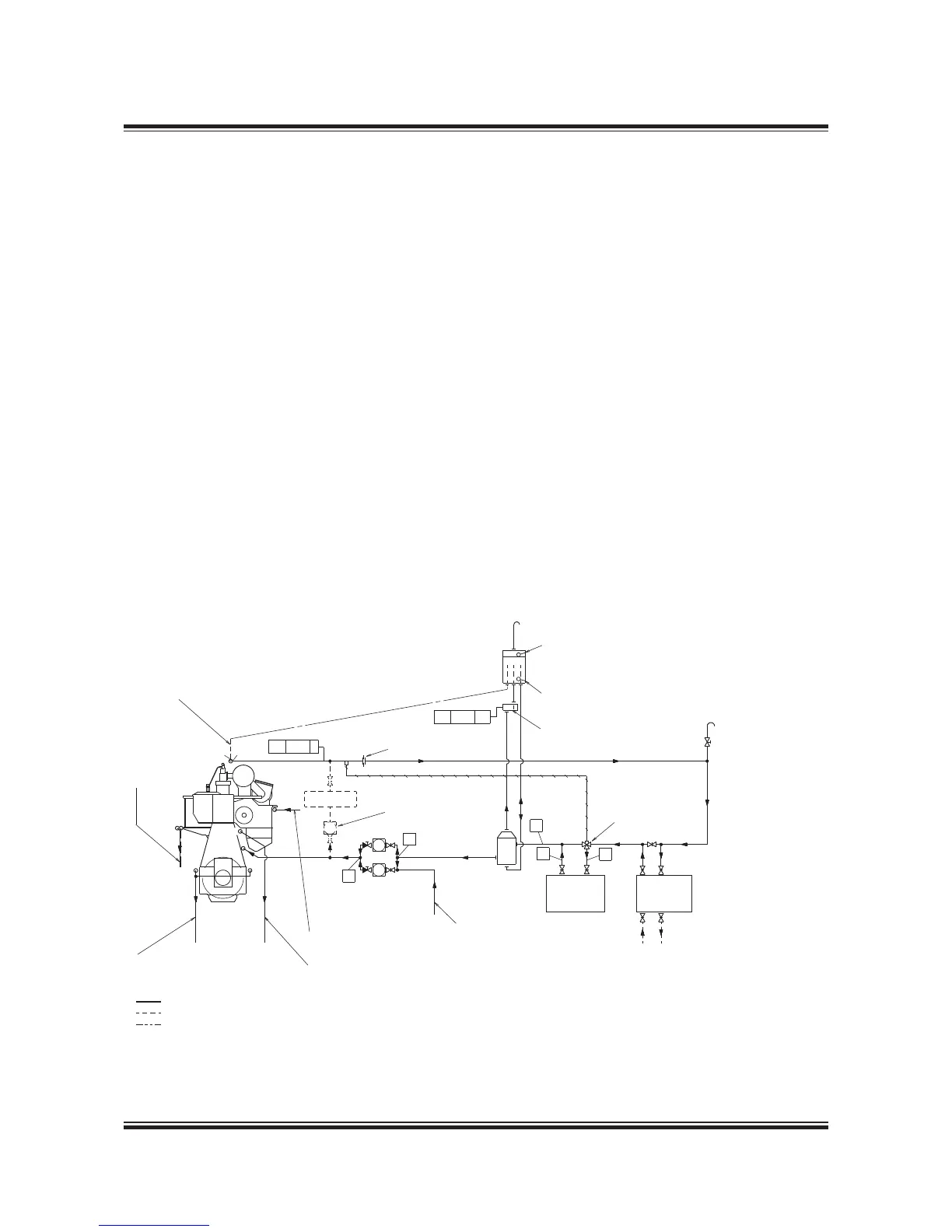
Jacket Cooling Water System
The jacket cooling water system is used for cool-
ing the cylinder liners, cylinder covers and ex-
haust valves of the main engine and heating of the
fuel oil drain pipes, see Fig. 12.05.01.
The jacket water pump) draws water from the
jacket water cooler outlet and delivers it to the
engine.
At the inlet to the jacket water cooler there is a
thermostatically controlled regulating valve, with
a sensor at the engine cooling water outlet, which
keeps the main engine cooling water outlet at a
temperature of 80 °C.
The engine jacket water must be carefully treated,
maintained and monitored so as to avoid corro-
sion, corrosion fatigue, cavitation and scale for-
mation. It is recommended to install a preheater
if preheating is not available from the auxiliary
engines jacket cooling water system.
The venting pipe in the expansion tank should end
just below the lowest water level, and the expan-
sion tank must be located at least 5 m above the
engine cooling water outlet pipe.
The freshwater generator, if installed, may be con-
nected to the seawater system if the generator
does not have a separate cooling water pump.
The generator must be coupled in and out slowly
over a period of at least 3 minutes.
For external pipe connections, we prescribe the
following maximum water velocities:
Jacket water ................................................ 3.0 m/s
Seawater ..................................................... 3.0 m/s
Fig. 12.05.01: Jacket cooling water system
178 50 172.5
 Loading...


