MAN B&W 6.04
Page of 2
MAN Diesel
198 61 71-5.0
MAN B&W S46MC-C8, S42MC7, S35MC7,
L35MC6, S26MC6
Auxiliary Machinery Capacities
The dimensioning of heat exchangers (coolers)
and pumps for derated engines can be calculated
on the basis of the heat dissipation values found
by using the following description and diagrams.
Those for the nominal MCR (L
), may also be used
if wanted.
The nomenclature of the basic engine ratings and
coolers, etc. used in this section is shown in Fig.
6.0.0 and 6.0.02.
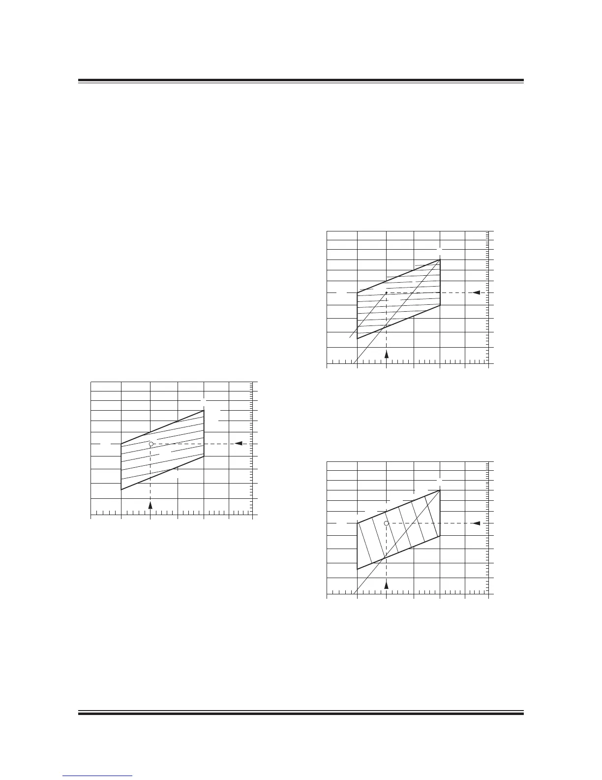
Cooler heat dissipations
For the specied MCR (M) the following three dia-
grams in Figs. 6.04.0, 6.04.02 and 6.04.03 show
reduction factors for the corresponding heat dis-
sipations for the coolers, relative to the values
stated in the ‘List of Capacities’ valid for nominal
MCR (L
).
The percentage power (P
M%
) and speed (n
M%
) of L
ie: P
M%
= P
M
/P
L
x 00%
n
M%
= n
M
/n
L
x 00%
for specied MCR (M) of the derated engine is
used as input in the abovementioned diagrams,
giving the % heat dissipation gures relative to
those in the ‘List of Capacities’,
Q
air%
= 00 x (P
M
/P
L
)
.68
x (n
M
/n
L
)
– 0.83
x k
O
k
O
= + 0.27 x ( – P
O
/P
M
) =
178 53 75-3.1
Fig. 6.04.01: Scavenge air cooler, heat dissipation Q
air%
in
point M, in % of the L
1
value Q
air, L1
and valid for P
O
= P
M
..
As optimising point O = M, correction k
O
= 1
Q
jw%
= e
(– 0.08 x ln (n
M%
)
+ 0.8072 x ln (P
M%
) + .264)
Fig. 6.04.02: Jacket water cooler, heat dissipation Q
jw%
in point M, in % of the L
1
value Q
jw, L1
178 54 64-0.1
Q
lub%
= 67.3009 x ln (n
M%
) + 7.6304 x ln (P
M%
)
245.074
Fig. 6.04.03: Lubricating oil cooler, heat dissipation
Q
lub%
in point M, in % of the L
1
value Q
lub, L1
178 53 77-7.1
 Loading...


