MAN B&W 7.04
Page 3 of 3
MAN Diesel
198 67 75-7.1MAN B&W S35MC. S35MC-C, L35MC, S26MC
Fuel Oil Pipe Heat Tracing
184 20 33-2.0.0b
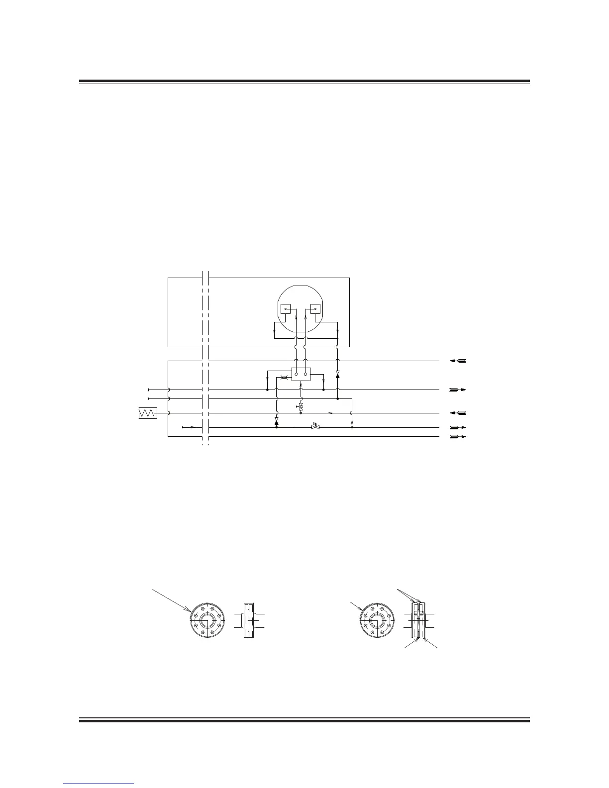
Fig. 7.04.03: Fuel oil pipe heat tracing
The letters refer to list of ‘Counterflanges’
AftFore
BX
AF
X
F
BF
The steam tracing of the fuel oil pipes is intended
to operate in two situations:
1. When the circulation pump is running, there
will be a temperature loss in the piping, see
Fig. 7.04.02. This loss is very small, therefore
tracing in this situation is only necessary with
very long fuel supply lines.
2. When the circulation pump is stopped with
heavy fuel oil in the piping and the pipes have
cooled down to engine room temperature, as
it is not possible to pump the heavy fuel oil.
In this situation the fuel oil must be heated to
pumping temperature of about 50 ºC.
To heat the pipe to pumping level we recom-
mend to use 100 watt leaking/meter pipe.
178 52 555.2
Fig. 7.04.04b: Spray Shields by clamping bands
In order to fulfil IMO regulations, fuel oil and lubri-
cating oil pipe assemblies are to be enclosed by
spray shields as shown in Fig. 7.04.04a and b.
Antisplashing tape Clamping bands
Plate 0,5 mm. thickness
The tape is to be wrapped in accordance with
the makers instruction for class approval
The width is to cover
head of bolts and nuts
Overlap
Fig. 7.04.04a: Spray Shields by anti-splashing tape
To avoid leaks, the spray shields are to be in-
stalled after pressure testing of the pipe system.
Fuel Oil and Lubricating Oil Pipe Spray Shields
 Loading...


