MAN B&W 14.02
Page 2 of 3
MAN Diesel
MAN B&W MC/MCC, ME-B engines 198 65 86-2.3
Control of the Auxiliary Blowers
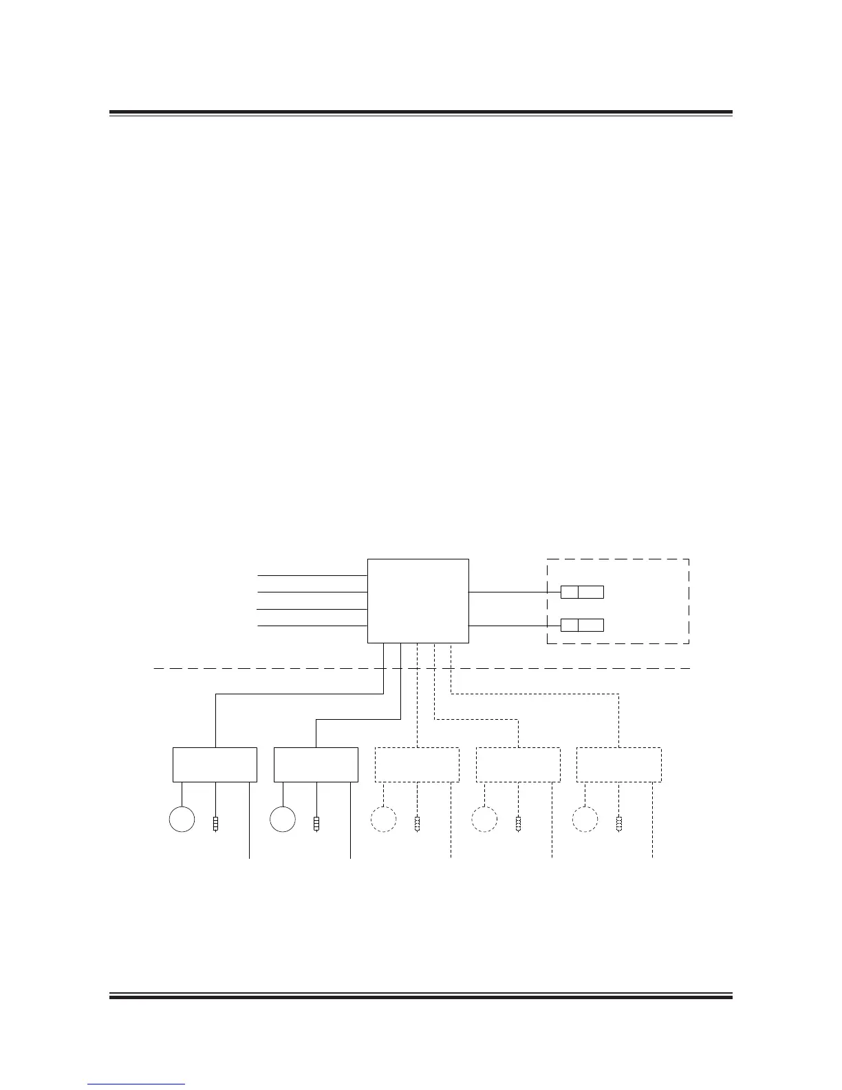
The auxiliary blowers are fitted onto the main en-
gine and controlled by a system comprising:
1 pc Control Panel
1 pc Starter Panel per Auxiliary Blower
2 pc Pressure Switches
Referring to the diagram of the auxiliary blower
control system, Fig. 14.02.02:
• The Control Panel controls the run/stop signals
to all Auxiliary Blower Starter Panels. The Con-
trol Panel consists of an operation panel and a
terminal row interconnected by a 1,200 mm long
wire harness.
• The Auxiliary Blower Starter Panels control and
protect the Auxiliary Blower motors, one panel
with starter per blower.
• The pressure switch ‘P’ controls the run/stop
signals, while pressure switch ‘B’ is part of the
auxiliary blower alarm circuit.
The control panel is yard’s supply. It can be or-
dered as an option: 4 55 650.
The starter panels with starters for the auxiliary
blower motors are not included, they can be or-
dered as an option: 4 55 653. (The starter panel
design and function is according to MAN Diesel’s
diagram, however, the physical layout and choice
of components has to be decided by the manu-
facturer).
Heaters for the blower motors are available as an
option: 4 55 155.
Fig. 14.02.02: Diagram of auxiliary blower control system
 Loading...


