MAN B&W 7.06
Page 2 of 2
MAN Diesel
MAN B&W MC/MC-C, ME/ME-C/ME-GI/ME-B engines 198 38 828.3
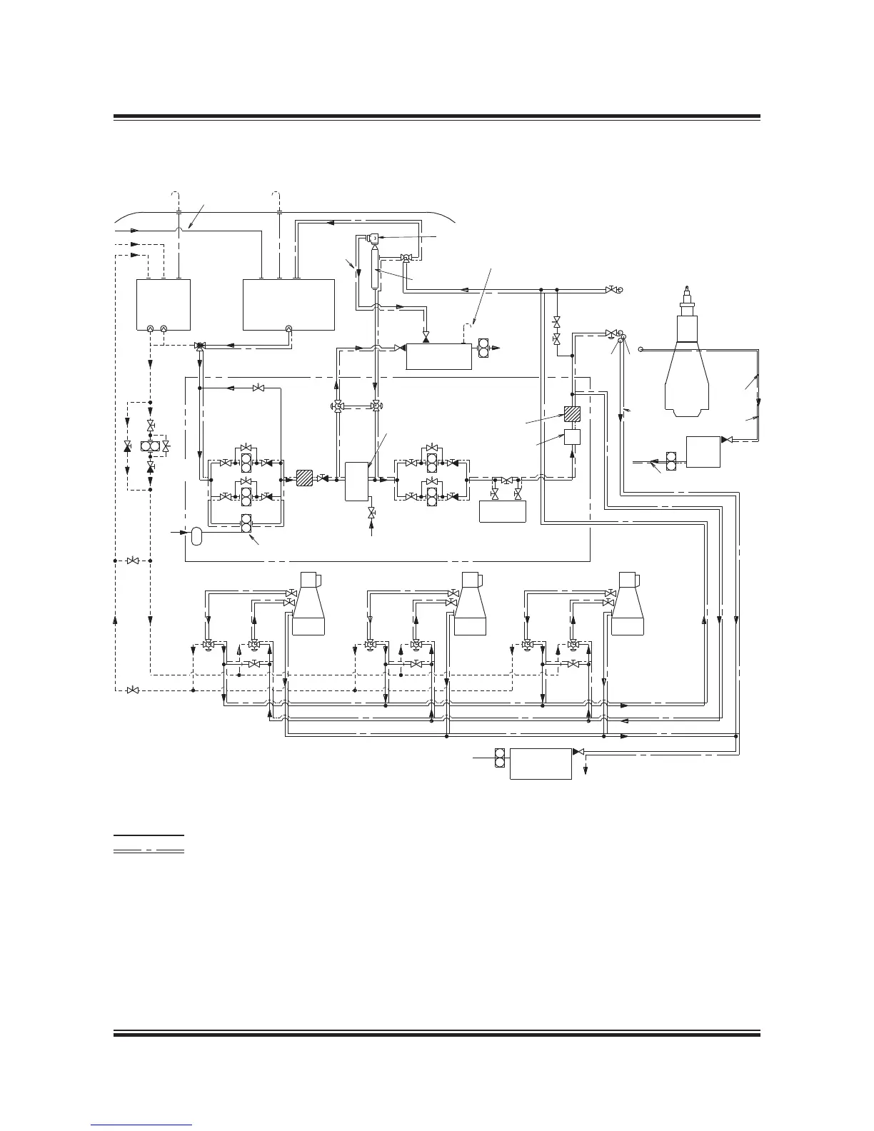
– – – – – – – – – Diesel oil
Heavy fuel oil
Heated pipe with insulation
a) Tracing fuel oil lines: Max. 150 °C
b) Tracing fuel oil drain lines: Max. 90 °C,
min. 50 °C for installations with jacket cooling water
Number of auxiliary engines, pumps, coolers, etc.
are subject to alterations according to the actual
plant specification.
The letters refer to the list of ‘Counterflanges’.
Fig. 7.06.01: System for emulsification of water into the fuel common to the main engine and MAN Diesel GenSets
198 99 018.3
From
centrifuges
Deck
Diesel
oil service
tank
Heavy fuel oil
service tank
Overflow valve
adjusted to
12 bar
Supply pumps
Filter
Booster
pump
Compressed
air
‘S’
Safety pump
air operated
Fresh water
supply
To special
safety tank
Automatic
deaerating
valve
Venting box
Common fuel oil supply unit
Homogeniser
Full flow
filter
Water in oil
measuring
Circulating
pumps
Heater
BX F
BF
X
AD
AF
BD
b)
a)
32 mm
Nom.
bore
Main engine
F.O.
drain
tank
To HFO service
or settling tank
A2
A1
A3
GenSet
A2
A1
A3
GenSet
A2
A1
A3
GenSet
To HFO service
or settling tank
Fuel oil
sludge tank
To freshwater cooling
pump suction
F. O. special
safety tank
Deaerating to be
controlled against
expansion of water
To HFO
service or
settling tank
Supply air tank
 Loading...


