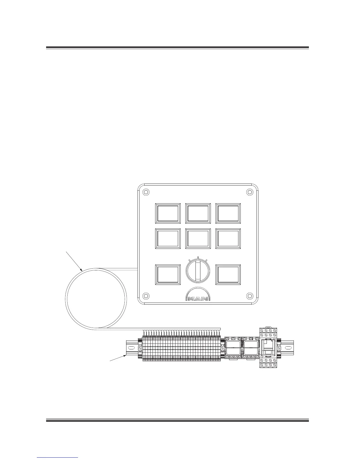
1,200mm wire harness,
shielded by 20mm jacket
Harness to be fixed to structure
MAIN ENGINE
AUXILIARY BLOWER CONTROL
K5 K7K10
AUXILIARY
BLOWER 3
RUNNING
AUXILIARY
BLOWER 1
RUNNING
AUXILIARY
BLOWER 2
RUNNING
AUXILIARY
BLOWER 5
RUNNING
AUXILIARY
BLOWER 6
RUNNING
IN SERVICE
LAMP TEST
OFF MANUAL
AUTO
AUXILIARY
BLOWER 4
RUNNING
Terminal row, to be mounted in
the Manoeuvring Console
512 36 604.0.0
Fig. 14.02.03: Control panel including operation panel, wiring harness and terminal row, option: 4 55 650
Operation Panel for the Auxiliary Blowers
On the operation panel, three control modes are
available to run/stop the blowers:
• AUTO – Run/stop is automatically controlled by
scavenge air pressure
• MANUAL – Start of all blowers in sequence at
intervals of 6 sec
• OFF – The auxiliary blowers are stopped after a
set period of time, 30 sec for instance.
The operation panel and terminal row have to be
mounted in the Engine Control Room Manoeu-
vring Console, see Section 16.01.
The control panel for the auxiliary blowers includ-
ing the operation panel, wiring harness and termi-
nal row is shown in Fig. 14.02.03.
 Loading...


