MAN B&W 16.01
Page 1 of 11
MAN Diesel
MAN B&W MC/MC-C engines 198 56 34-8.2
Engine Control System
The engine is provided with a pneumatic/electric
manoeuvring and fuel oil regulating system, which
transmits orders from the separate manoeuvring
consoles to the engine.
By means of the regulating system it is possible
to start, stop, reverse the engine and control the
engine speed. The speed setting device on the ma-
noeuvring consoles gives a speed setting signal to
the governor, dependent on the desired number of
rpm.
At shutdown, the fuel injection is stopped by
activating the puncture valves in the fuel pumps,
independent of the speed position of the speed
setting device.
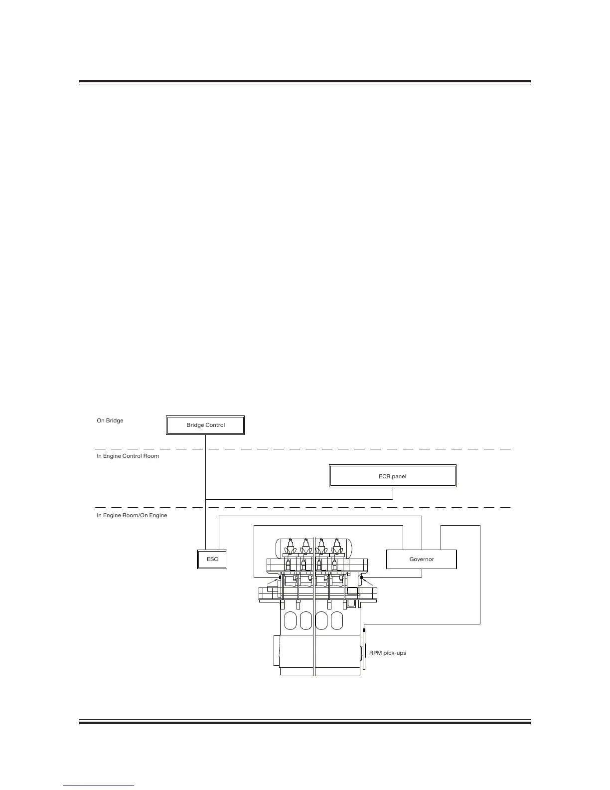
The layout of the Engine Control System is shown
in Fig. 16.01.01 and a diagram of the pneumatic
manoeuvring system in Fig. 16.01.02.
Manoeuvring Consoles
The Engine Control System for the MC / MC-C
engine is prepared for conventional remote con-
trol, having an interface to the Bridge Control (BC)
system and the Engine Side Console (ESC).
The main Engine Control Room (ECR) manoeu-
vring console is to be located in the engine con-
trol room. The console with buttons, lamps, etc.
recommended by MAN Diesel is shown in Fig.
16.01.07. Components for remote control for a
typical installation with bridge control is shown in
Fig. 16.01.05.
The layout of the Engine Side Console and instru-
ment panel is shown in Fig. 16.01.06a, b and c.
The console and an electronic speed setting
device, the governor, are located on the manoeu-
vring side of the engine.
In the event of breakdown of the normal pneumat-
ic/electric manoeuvring system, the engine can be
operated from the Engine Side Console.
 Loading...


