MAN B&W 6.02
Page 1 of 1
MAN Diesel
198 74 63-3.0MAN B&W MC/MC-C/ME/ME-C/ME-B/ME-GI-TII engines
List of Capacities and Cooling Water Systems
The capacities for the starting air receivers and
the compressors are stated in Fig. 6.03.01.
Heat radiation and air consumption
The radiation and convection heat losses to the
engine room is around 1% of the engine nominal
power (kW in L
1
).
The air consumption is approximately 98.2%
of the calculated exhaust gas amount, ie.
M
air
= M
exh
x 0.982.
Flanges on engine, etc.
The location of the flanges on the engine are
shown in: ‘Engine pipe connections’, and the flang-
es are identified by reference letters stated in the
‘List of flanges’; both can be found in Chapter 5.
The diagrams use the ‘Basic symbols for piping’,
whereas the symbols for instrumentation accord-
ing to ‘ISO 12191’ and ‘ISO 12192’ and the in-
strumentation list found in Appendix A.
178 11 264.1
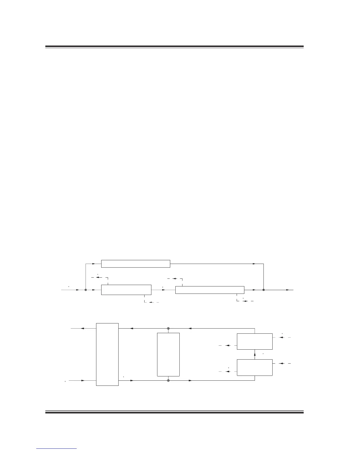
Fig. 6.02.01: Diagram for seawater cooling system
Fig. 6.02.02: Diagram for central cooling water system
178 11 276.1
The List of Capacities contain data regarding the
necessary capacities of the auxiliary machinery
for the main engine only, and refer to a nominally
rated engine. Complying with IMO Tier II NO
x
limi-
tations.
The heat dissipation figures include 10% extra
margin for overload running except for the scav-
enge air cooler, which is an integrated part of the
diesel engine.
Cooling Water Systems
The capacities given in the tables are based on
tropical ambient reference conditions and refer to
engines with high efficiency/conventional turbo-
charger running at nominal MCR (L
1
) for:
• Seawater cooling system,
See diagram, Fig. 6.02.01 and nominal capaci-
ties in Fig. 6.03.01
• Central cooling water system,
See diagram, Fig. 6.02.02 and nominal capaci-
ties in Fig. 6.03.01
 Loading...


