MAN B&W 2.04
Page 6 of 10
MAN Diesel
198 69 94-7.1MAN B&W MC/MC-C-TII engines
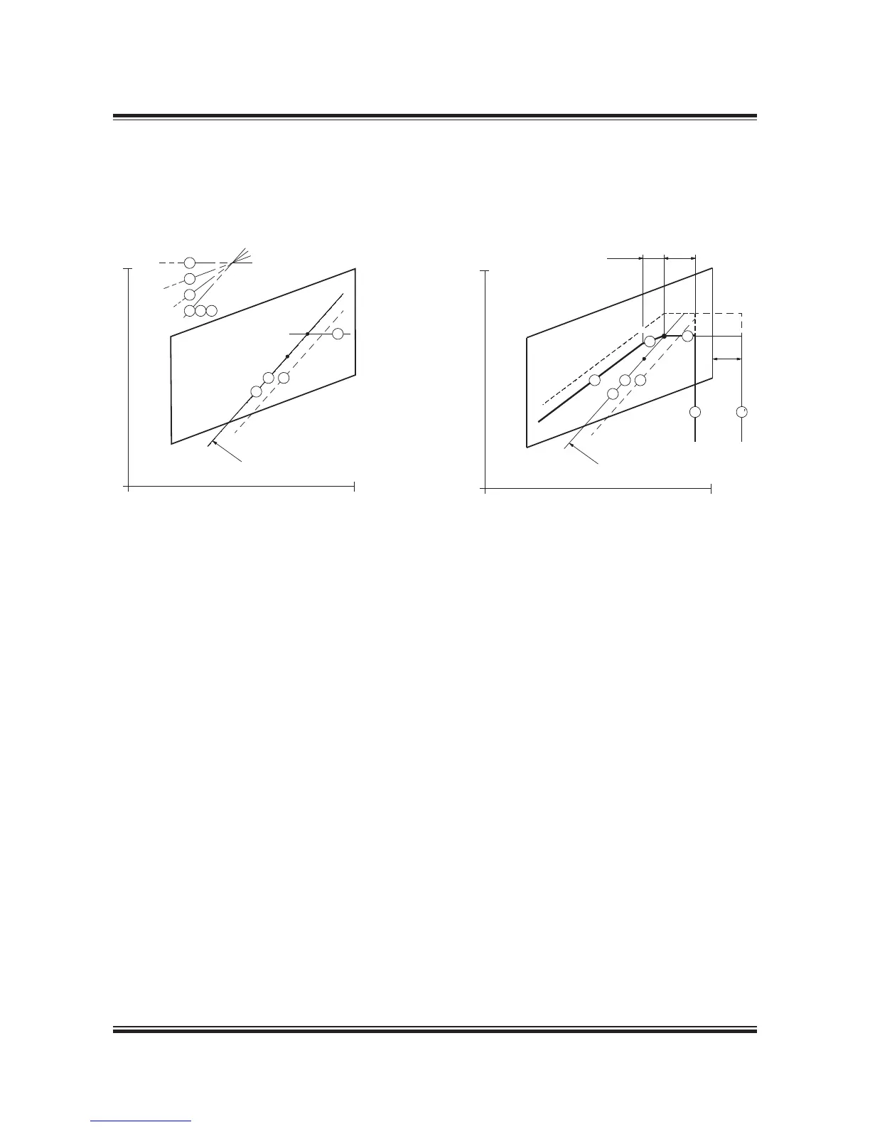
Example 1: Normal running conditions.
Engine coupled to a fixed pitch propeller (FPP) and without a shaft generator
M Specified MCR of engine
S Continuous service rating of engine
O Optimising point of engine
A Reference point of load diagram
MP Specified MCR for propulsion
SP Continuous service rating of propulsion
Point A of the load diagram is found:
Line 1 Propeller curve through optimising point (O)
is equal to line 2
Line 7 Constant power line through specified MCR (M)
Point A Intersection between line 1 and 7
Fig. 2.04.04: Normal running conditions. Engine coupled to a fixed pitch propeller (FPP) and without a shaft generator
178 39 20-6.0
The specified MCR (M) and optimising point O and its propel-
ler curve 1 will normally be selected on the engine service
curve 2 (for fouled hull and heavy weather), as shown in the
layout diagram.
Point A is then found at the intersection between propeller
curve 1 (2) and the constant power curve through M, line 7. In
this case, point A is equal to point M and point O.
Layout diagram Load diagram
Once point A has been found in the layout diagram, the load
diagram can be drawn, as shown in the above figure, and
hence the actual load limitation lines of the diesel engine may
be found by using the inclinations from the construction lines
and the %figures stated.
Propulsion and engine
service curve for fouled
hull and heavy weather
Engine speed, % of L
1
100%
Power, % of L
1
100%
7
5
4
1
2 6
1
2
6
7
A=O=M=MP
S=SP
 Loading...


