178 31 598.1r
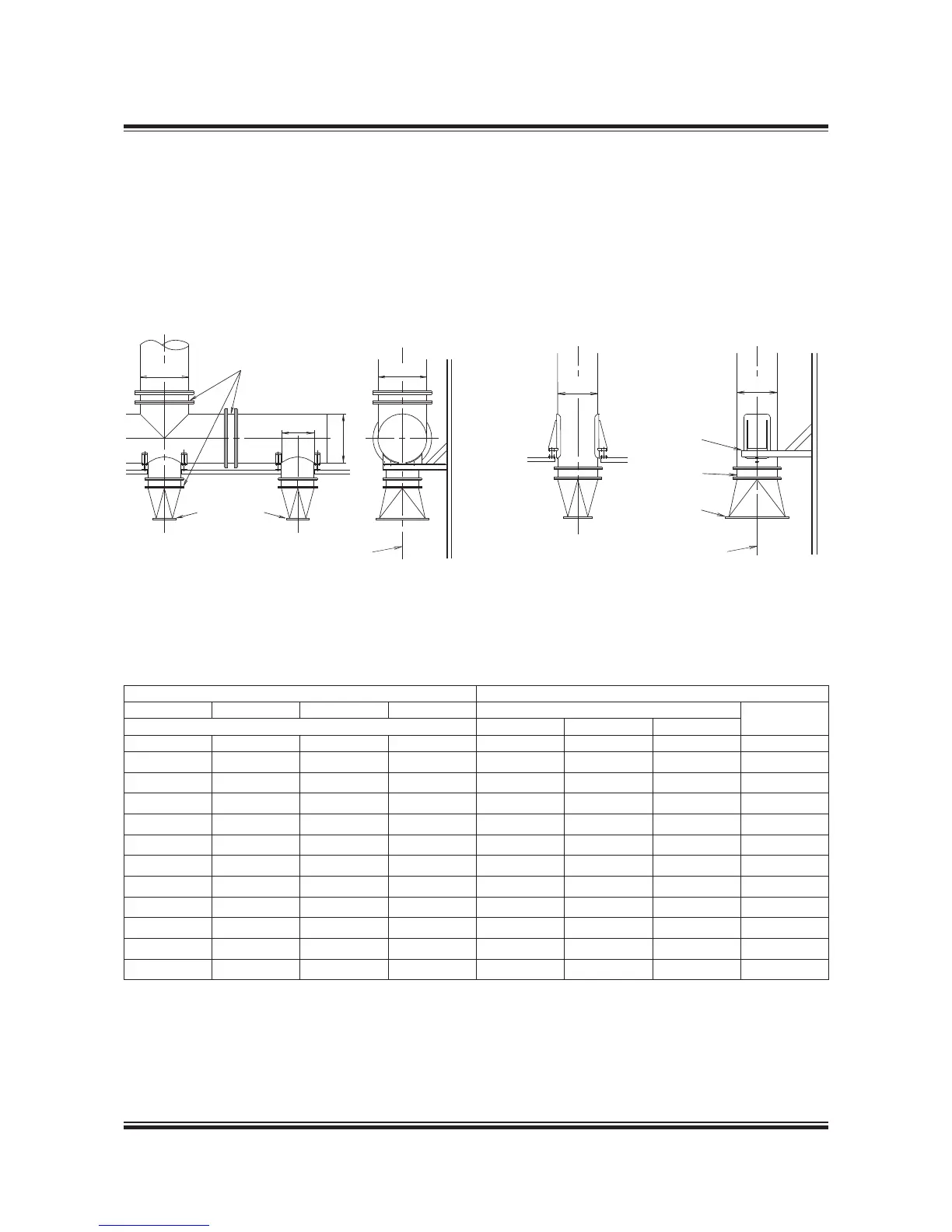
Fig. 15.07.01a: Exhaust pipe system, with turbocharger
located on exhaust side of engine, option: 4 59 123
Fig. 15.07.01b: Exhaust pipe system, with single turbo-
charger located on aft end of engine, option: 4 59 121
Gas velocity Exhaust gas pipe diameters
35 m/s 40 m/s 45 m/s 50 m/s D0 D4
Gas mass ow 1 T/C 2 T/C 3 T/C
kg/s kg/s kg/s kg/s [DN] [DN] [DN] [DN]
0.4 .9 3.4 4.9 750 550 N.A. 750
.9 3.6 5.3 7.0
800 550 N.A. 800
3.4 5.3 7.2 9.
850 600 500 850
5.0 7.2 9.3 2.5
900 650 500 900
6.7 9. 2.5
23.9 950 650 550 950
8.6 2.2
23.9 26.5 ,000 700 600 ,000
20.5 23.4 26.3 29.2 ,050 750 600 ,050
22.4 25.7 28.9 32. ,00 800 650 ,00
24.5 28.0 3.5 35. ,50 800 650 ,50
26.7 30.5 34.3 38.2 ,200 850 700 ,200
3.4
35.8 40.3 44.8 ,300 900 750 ,300
Table 15.07.02: Exhaust gas pipe diameters and exhaust gas mass ow at various velocities
The exhaust gas pipe diameters listed in Table
5.07.02 are based on the exhaust gas ow ca-
pacity according to ISO ambient conditions and
an exhaust gas temperature of 250 ºC.
The exhaust gas velocities and mass ow listed
apply to collector pipe D4. The table also lists the
diameters of the corresponding exhaust gas pipes
D0 for various numbers of turbochargers installed.
 Loading...


