Home
Man
Engine
B&W L35MC6-TII
Man B&W L35MC6-TII User Manual
5
of 1
of 1 rating
375 pages
Give review
Manual
Specs
To Next Page
To Next Page
To Previous Page
To Previous Page
Loading...
MAN B
&W
5.07
Page of
MAN Diesel
MA
N B&
W L3
5MC
6
198 6
6 49
-
8.0
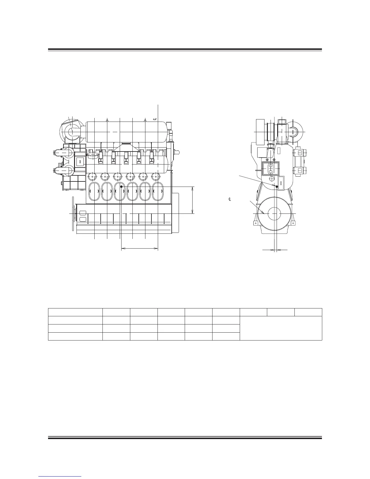
Fig. 5.07
: Ce
ntre o
f gr
avit
y
178 22 06-1.
1
#Y
Læ
#E
NTR
EæOFæGR
AVIT
Y
#R
ANK
SHA
FTæ
9
8
:
Cent
re of G
ravit
y
No. o
f cy
li
nd
er
s
5
6
7
8
9
10
1
1
12
Distance X mm
,420
,720
2,060
2,30
2,605
Available on r
equest
Distance Y mm
,270
,280
,330
,340
,330
Distance Z mm
0
5
5
20
20
All values stated are appr
oximate
110
112
Table of Contents
Table of Contents
3
Calculation of Capacities
11
Engine Layout and Load Diagrams
12
List of Capacities and Cooling Water Systems
14
Propeller Diameter and Pitch, Influence on Optimum Propeller Speed
15
The MC/MC-C Tier II Engine
16
Engine Design
19
The MC/MC-C Tier II Engine Design
21
Concept of the MC/MC-C Engine
21
Engine Design and IMO Regulation Compliance
21
Engine Type Designation
23
Power, Speed and Lubricating Oil
24
Engine Power Range and Fuel Oil Consumption
25
Lubricating Oil Data
25
Specific Fuel Oil Consumption
25
Layout Diagram for Engine Power and Speed
25
Performance Curves
26
MC Engine Description
27
Bedplate and Main Bearing
27
Frame Box
27
Cylinder Frame and Stuffing Box
27
Cylinder Liner/Cover
28
Crankshaft
28
Thrust Bearing
28
Turning Gear and Turning Wheel
28
Connecting Rod
29
Piston
29
Crosshead
29
Scavenge Air System/Cooler
29
Auxiliary Blower
30
Exhaust Gas System/Turbocharger
30
Camshaft and Cams
30
Chain/Indicator Drive
30
Governor
31
Fuel Oil Pump and Fuel Oil High Pressure Pipes
31
Fuel Valves and Starting Air Valve
31
Starting Air System
31
Exhaust Valve
32
Cylinder Lubrication
32
Manoeuvring System
32
Reversing
32
Piping Arrangements
33
Engine Cross Section of L35MC6
34
Engine Layout and Load Diagrams, SFOC
35
Engine Layout and Load Diagrams
37
Introduction
37
Propulsion and Engine Running Points
37
Propeller Curve
37
Fouled Hull
38
Engine Layout
38
Engine Margin
38
Constant Ship Speed Lines
38
Propeller Diameter and Pitch, Influence on the Optimum Propeller Speed
39
Influence of Diameter and Pitch on Propeller Design
39
Layout Diagram and Constant Ship Speed Lines
40
Layout Diagram Sizes
41
Engine Layout Diagram
42
Specified Maximum Continuous Rating
42
Continuous Service Rating
42
Optimising Point
42
Engine Load Diagram
43
Definitions
43
Operating Curves and Limits for Continuous Operation
43
Standard Engine Load Diagram
43
Limits for Overload Operation
44
Limits for Low Load Operation
44
Recommendation
44
Load Diagram for Ships Operating in Extreme Heavy Running Conditions
45
Examples of the Use of the Load Diagram
46
Load Diagram for Speed Derated Engine with Increased Light Running
46
Normal Running Conditions
47
Layout Diagram
47
Load Diagram
47
Special Running Conditions
48
Engine Coupled to a CPP with or Without a Shaft Generator
51
Diagram for Actual Project
53
Construction of Layout Diagram
53
Specific Fuel Oil Consumption, ME Versus MC Engines
54
SFOC for Conventional Turbochargers
55
Example of Part Load SFOC Curves for Conventional Turbochargers
55
SFOC Reference Conditions and Guarantee
56
Recommended Cooling Water Temperature During Normal Operation
56
Examples of Graphic Calculation of SFOC
57
SFOC Calculations for L35MC6
58
SFOC for L35MC6 with Fixed Pitch Propeller
59
SFOC for L35MC6 with Constant Speed
59
SFOC Calculations, Example
60
SFOC for Derated 6L35MC6
61
Fuel Consumption at an Arbitrary Load
62
SFOC at an Arbitrary Load
62
Emission Control
63
Turbocharger Selection & Exhaust Gas By-Pass
65
Turbocharger Selection
67
Conventional Turbochargers
67
Exhaust Gas By-Pass
68
Extreme Ambient Conditions
68
Arctic Running Condition
68
Emergency Running Condition
68
Total By-Pass of Exhaust for Emergency Running
69
Nox Reduction by SCR
70
Exhaust Gas Emission Control Today and Tomorrow
70
Layout of SCR System
71
Electricity Production
73
Electricity Production
75
Power Take off
75
Types of PTO
76
Designation of PTO
77
Pto/Rcf
78
Free Standing Generator, BW II/RCF
78
PTO with RENK Constant Frequency Gear
78
Extent of Delivery for BW II/RCF Units
79
Engine Preparations for PTO BW II
81
PTO Type: BW II/GCR
82
PTO Type: BW IV/GCR
82
Generic Outline of Power Take off (PTO) BW II/GCR
82
Tunnel Gear with Hollow Flexible Coupling
83
Generator Step-Up Gear
83
Flexible Coupling Integrated in the Shaft Line
83
Generic Outline of BW IV/GCR, Tunnel Gear
83
Auxiliary Propulsion System/Take Home System
84
Waste Heat Recovery Systems (WHR)
85
L16/24 Genset Data
86
List of Capacities for L16/24 1,000 Rpm, IMO Tier I
87
List of Capacities for L16/24 1,200 Rpm, IMO Tier I
88
L21/31 Genset Data
89
Power and Outline of L21/31
89
List of Capacities for L21/31, 1,000 Rpm, IMO Tier I
91
L23/30H Genset Data
92
Power and Outline of L23/30H
92
List of Capacities for L23/30H, 720/750 Rpm, IMO Tier I
93
List of Capacities for L23/30H, 900 Rpm, IMO Tier I
94
Installation Aspects
95
Installation Aspects
97
Space Requirements and Overhaul Heights
97
Overhaul of Engine
97
Space Requirement
98
Space Requirement for the Engine, Turbocharger on Aft End
98
Space Requirement for the Engine
99
Crane Beam for Overhaul of Turbocharger
100
Required Height and Distance and Weight
100
Crane Beam for Turbochargers
101
Crane Beam for Overhaul of Air Cooler
102
Engine Room Crane
102
Engine Room Crane
103
Overhaul with man B&W Double-Jib Crane
104
MAN B&W Double-Jib Crane
105
Gallery Outline
106
Engine Outline, Galleries and Pipe Connections
106
Engine and Gallery Outline
107
Centre of Gravity
111
Mass of Water and Oil
112
Water and Oil in Engine
112
Engine Pipe Connections
113
Counterflanges
114
Counterflanges
116
Counterflanges, Connection D
118
MAN Diesel Type TCA/TCR
118
ABB Type TPL/A100
119
MHI Type MET
120
Counterflanges, Connection E
121
MAN Diesel Type TCA
121
ABB Type TPL
122
Venting of Lubbricating Oil Discharge Pipe for Turbochargers
123
Engine Seating and Holding down Bolts
124
Epoxy Chocks Arrangement
125
Arrangement of Epoxy Chocks and Holding down Bolts
126
Engine Seating Profile
127
Profile of Engine Seating with Vertical Oil Outlet
127
Profile of Engine Seating with Horizontal Oil Outlet
128
Profile of Engine Seating, End Chocks
129
Engine Top Bracings
130
Mechanical Top Bracing
131
Hydraulic Top Bracing Arrangement
133
Components for Engine Control System
134
Shaftline Earthing Device
135
Scope and Field of Application
135
Design Description
135
Shaftline Earthing Device Installations
136
Connection of Cables for the Shaftline Earthing Device
136
Installation of Shaftline Earthing Device in an Engine Plant
136
MAN Diesel’s Alpha Controllable Pitch Propeller
138
VBS Type CP Propeller Designation and Range
138
Data Sheet for Propeller
139
Dimension Sketch for Propeller Design Purposes
139
Main Dimensions
140
Propeller Clearance
140
Propeller Design Purposes
140
Servo Oil System for VBS Type CP Propeller
141
Hydraulic Power Unit for Alpha CP Propeller
142
Alphatronic 2000 Propulsion Control System
143
Propulsion Control Station on the Main Bridge
144
Main Bridge Station Standard Layout
144
Renk KAZ Clutch for Auxilliary Propulsion Systems
145
Further Information about Alpha CP Propeller
145
List of Capacities: Pumps, Coolers & Exhaust Gas
147
Calculation of List of Capacities and Exhaust Gas Data
149
Nomenclature
149
Engine Configurations Related to SFOC
149
List of Capacities and Cooling Water Systems
150
Heat Radiation and Air Consumption
150
Flanges on Engine, Etc
150
Diagram for Seawater Cooling System
150
List of Capacities for 5L35MC6-TII at NMCR - IMO no
151
Fuel
151
List of Capacities for 6L35MC6-TII at NMCR - IMO no
152
List of Capacities for 7L35MC6-TII at NMCR - IMO no
153
List of Capacities for 8L35MC6-TII at NMCR - IMO no
154
List of Capacities for 9L35MC6-TII at NMCR - IMO no
155
List of Capacities for 10L35MC6-TII at NMCR - IMO no
156
List of Capacities for 11L35MC6-TII at NMCR - IMO no
157
List of Capacities for 12L35MC6-TII at NMCR - IMO no
158
Auxiliary Machinery Capacities
159
Cooler Heat Dissipations
159
Scavenge Air Cooler
159
Jacket Water Cooler
159
Pump Capacities
160
Seawater Cooling System
160
Central Cooling Water System
160
Pump Pressures
160
Calculation of List of Capacities for Derated Engine
161
Freshwater Generator
163
Calculation Method
163
Jacket Cooling Water Temperature Control
164
Jacket Cooling Water Heat Recovery Flow Diagram
164
Calculation of Freshwater Production for Derated Engine
165
Exhaust Gas Amount and Temperature
166
Influencing Factors
166
Summarising Equations for Exhaust Gas Amounts and Temperatures
166
Correction of Exhaust Gas Data for Ambient Conditions
167
Exhaust Gas Correction Formula for Ambient Conditions
168
Change of Specific Exhaust Gas Amount
168
Change of Exhaust Gas Temperature
168
Calculation of Exhaust Data for Derated Engine
169
Fuel
171
Pressurised Fuel Oil System
173
Design Parameters
173
Fuel Pumps and Drain
173
Fuel Oil System
174
Fuel Considerations
175
Constant Operation on Heavy Fuel
175
Heating of Fuel Drain Pipe
175
Fuel Flow Velocity and Viscosity
175
Fuel Oil System
175
Fuel Oils
176
Heavy Fuel Oil (HFO)
176
Guiding Heavy Fuel Oil Specification
176
Fuel Oil Pipes and Drain Pipes
177
Fuel Oil Pipe Insulation
178
Flanges and Valves
178
Mounting
178
Heat Loss in Piping
179
Fuel Oil Pipe Heat Tracing
180
Fuel Oil and Lubricating Oil Pipe Spray Shields
180
Spray Shields by Anti-Splashing Tape
180
Spray Shields by Clamping Bands
180
Components for Fuel Oil System
181
Fuel Oil Centrifuges
181
Fuel Oil Supply Pump
181
Fuel Oil Circulating Pump
181
Fuel Oil Heater
182
Fuel Oil Heating Chart
182
Fuel Oil Filter
183
Fuel Oil Venting Box
183
Flushing of the Fuel Oil System
183
Water in Fuel Emulsification
184
Temperature and Pressure
184
Safety System
184
Impact on the Auxiliary Systems
184
System for Emulsification of Water into the Fuel
185
Lubricating Oil
187
Lubricating and Cooling Oil System
189
Lubrication of Turbochargers
189
Lubricating and Cooling Oil Pipes
190
Lubricating Oil Pipes for Turbochargers
192
MAN Diesel Turbocharger Type TCA
192
ABB Turbocharger Type TPL
192
Mitsubishi Turbocharger Type MET
193
Lubricating Oil Centrifuges and List of Lubricating Oils
194
Components for Lubricating Oil System
195
Lubricating Oil Pump
195
Lubricating Oil Cooler
195
Lubricating Oil Temperature Control Valve
195
Lubricating Oil Full Flow Filter
196
Flushing of Lube Oil System
196
Lubricating Oil Outlet
197
Lubricating Oil Tank
198
Lubricating Oil Tank Operating Conditions
199
Crankcase Venting and Bedplate Drain Pipes
202
Cylinder Lubrication
203
Cylinder Lubricating Oil System
205
Cylinder Lubricators and Service Tank
205
Cylinder Oils
205
Cylinder Oil Feed Rate
205
MAN B&W Alpha Cylinder Lubrication System
206
System Control Units
206
Alpha Adaptive Cylinder Oil Control
207
Working Principle
207
Basic and Minimum Setting with Alpha ACC
207
Cylinder Lubricating Oil Dosage with Alpha ACC at All Loads
207
Pump Station and man B&W Alpha Cylinder Lubricators on Engine
208
Cylinder Lubricating Oil Supply System for Two Different BN Oils
208
MAN B&W Alpha Cylinder Lubricators with Piping and Instrumentation
208
Lubricator Control System
209
Control of the man B&W Alpha Cylinder Lubrication System
209
Wiring Diagram for man B&W Alpha Cylinder Lubrication System
210
Mechanical Cylinder Lubricators
211
Piping and Instrumentation for a Mechanical Cylinder Lubricator
211
Load Change Dependent Mechanical Lubricator
211
Cylinder Lubricating Oil Supply System
212
Piston Rod Stuffing Box Drain Oil
213
Stuffing Box Drain Oil System
216
Central Cooling Water System
217
Components for Central Cooling Water System
221
Seawater Cooling Pumps
221
Central Cooler
221
Central Cooling Water Pumps
221
Jacket Water System
222
Jacket Water Cooling Pump
222
Seawater Cooling
223
Seawater Systems
225
Seawater Cooling Pipes
227
Components for Seawater Cooling System
228
Seawater Cooling Pump
228
Seawater Thermostatic Valve
228
Jacket Cooling Water System
229
Jacket Cooling Water Pipes
230
Components for Jacket Cooling Water System
231
Jacket Water Thermostatic Valve
231
Jacket Water Preheater
231
Deaerating Tank
231
Temperature at Start of Engine
233
Preheating of Diesel Engine
233
Normal Start of Engine
233
Start of Cold Engine
233
Starting and Control Air
235
Starting and Control Air Systems
237
Components for Starting Air System
238
Starting Air Compressors/Receivers
238
Reduction Station for Control and Safety Air
238
Turning Gear
238
Starting and Control Air Pipes
239
Exhaust Valve Air Spring Pipes
240
Electric Motor for Turning Gear
241
Scavenge Air
243
Scavenge Air System
245
Exhaust Gas
245
Auxiliary Blowers
246
Emergency Running
246
Scavenge Air Cooler Requirements
246
Influence of Ambient Temperature Conditions
246
Control of the Auxiliary Blowers
247
Diagram of Auxiliary Blower Control System
247
Operation Panel for the Auxiliary Blowers
248
Control Panel
248
Scavenge Air Pipes
249
Electric Motor for Auxiliary Blower
250
Scavenge Air Cooler Cleaning System
251
Drain from Water Mist Catcher
251
Auto Pump Overboard System
251
Air Cooler Cleaning Pipes
251
Air Cooler Cleaning Unit
252
Scavenge Air Box Drain System
253
Fire Extinguishing System for Scavenge Air Space
254
Fire Extinguishing Pipes in Scavenge Air Space
255
Exhaust Gas
257
Exhaust Gas System
259
Exhaust Gas Pipes
260
Cleaning Systems
261
Exhaust Gas System for Main Engine
262
Components of the Exhaust Gas System
263
Exhaust Gas Compensator after Turbocharger
263
Exhaust Gas Boiler
263
Exhaust Gas Silencer
264
Spark Arrester
264
Calculation of Exhaust Gas Back-Pressure
265
Exhaust Gas Data
265
Exhaust Gas Velocity
265
Pressure Losses Across Components
265
Measuring Back Pressure
266
Pressure Losses and Coefficients of Resistance in Exhaust Pipes
267
Forces and Moments at Turbocharger
268
Turbocharger Located on Aft End
268
Vectors of Thermal Expansion
268
Max. Expected Movements of the Exhaust Gas Flange
268
Two Turbochargers Located on Exhaust Side
269
Forces and Moments on the Turbochargers’ Exhaust Gas Outlet Flange
270
The Max. Permissible Forces
270
Diameter of Exhaust Gas Pipes
271
Exhaust Pipe Systems
271
Exhaust Gas Pipe Diameters and Exhaust Gas Mass Flow
271
Engine Control System
273
Engine Control System
275
Manoeuvring Consoles
275
Engine Control System Layout
275
Diagram of Manoeuvring System
276
Manoeuvring System on Engine
277
Shut down System
277
Slow Turning
277
Control System for Plants with CPP
277
Sequence Diagram
278
Governor Parts and Mode of Operation
280
Governor for ‘Conventional’ Plants
280
Governor for ‘Advanced’ Plants
280
Governor and Remote Control Components
281
Electronic Governor
281
Components for Remote Control of Reversible Engine with FPP
281
Engine Side Control Console with Diagram
282
Diagram of Engine Side Control Console
282
Engine Side Control Console and Instrument Panel
283
Engine Control Room Console
284
Sequence Diagram for Engines with Fixed Pitch Propeller
285
Engine Control System Interface to Surrounding Systems
287
Alarm System
287
Telegraph System
287
Remote Control System
287
Power Management System
288
Auxiliary Equipment System
288
Engine Monitoring
288
Instrumentation
288
Vibration Aspects
289
Vibration Aspects
291
External Unbalanced Moments
291
2Nd Order Moments on 4, 5 and 6-Cylinder Engines
292
Compensator Solutions
292
Statistics of Vertical Hull Vibrations in Tankers and Bulk Carriers
292
Preparation for Compensators
293
Basic Design Regarding Compensators
293
1St Order Moments on 4-Cylinder Engines
294
Balancing 1St Order Moments
294
1St Order Moment Compensators
294
Electrically Driven Moment Compensator
295
MAN Diesel 2Nd Order Electrically Driven Moment Compensator
295
Compensation of 2Nd Order Vertical External Moments
296
Power Related Unbalance
297
Calculation of External Moments
297
Guide Force Moments
298
Top Bracing
298
Definition of Guide Force Moments
298
H-Type Guide Force Moment
298
Vibration Limits Valid for Single Order Harmonics
299
Axial Vibrations
301
Torsional Vibrations
301
Undercritical Running
301
Critical Running
302
Overcritical Running
302
External Forces and Moments, L35MC6 Layout Point L
303
Monitoring Systems and Instrumentation
305
Monitoring Systems and Instrumentation
307
PMI System
308
Measurements
308
PMI Type PT/S Off-Line
308
PMI System, Off-Line and On-Line Versions
309
Cocos-EDS Features
310
Connectivity
310
Cocos-EDS Sensor List
311
Alarm – Slow down and Shut down System
312
Basic Safety System Design and Supply
312
Alarm and Slow down System Design and Supply
312
Alarm, Slow down and Remote Indication Sensors
312
General Outline of the Electrical System
313
Panels and Sensors for Alarm and Safety Systems
313
Alarms for UMS – Class and man Diesel Requirements
314
Slow down for UMS – Class and man Diesel Requirements
317
Shut down for AMS and UMS – Class and man Diesel Requirements
318
Local Instruments
319
Other Alarm Functions
322
Drain Box for Fuel Oil Leakage Alarm
322
Bearing Condition Monitoring
322
Oil Mist Detector
322
Oil Mist Detector Pipes
323
Bearing Wear Monitoring System
324
Bearing Temperature Monitoring System
324
In the Extent of Delivery, There Are Three Options:
324
Water in Oil Monitoring System
325
Liner Wall Monitoring System
325
Control Devices
326
Identification of Instruments
327
Dispatch Pattern, Testing, Spares and Tools
329
Dispatch Pattern, Testing, Spares and Tools
331
Painting of Main Engine
331
Dispatch Pattern
331
Shop Trials/Delivery Test
331
Spare Parts
332
Wearing Parts
332
Tools
332
Specification for Painting of Main Engine
333
Dispatch Pattern, List of Masses and Dimensions
336
Shop Test
337
Minimum Delivery Test
337
List of Spare Parts, Unrestricted Service
338
Additional Spares
339
Large Spare Parts, Dimensions and Masses
348
List of Standard Tools for Maintenance
349
Dimensions and Masses of Tools
350
Tool Panels
359
Project Support and Documentation
363
Engine Selection Guides
363
Project Guides
363
Computerised Engine Application System (CEAS)
364
Extent of Delivery
365
Content of Extent of Delivery
365
Description of the ‘Extent of Delivery’
365
Copenhagen Standard Extent of Delivery
366
Installation Documentation
367
Engine-Relevant Documentation
367
Engine Room-Relevant Documentation
368
Engine Production and Installation-Relevant Documentation
370
Appendix
371
Appendix
373
Symbols for Piping
373
5
Based on 1 rating
Ask a question
Give review
Questions and Answers:
Need help?
Do you have a question about the Man B&W L35MC6-TII and is the answer not in the manual?
Ask a question
Man B&W L35MC6-TII Specifications
General
Brand
Man
Model
B&W L35MC6-TII
Category
Engine
Language
English
Related product manuals
Man B&W S80ME-C7
353 pages
Man B&W S50MC-C8-TII
403 pages
Man B&W S50ME-B9.3-TII
337 pages
Man E0834 E302
136 pages
Man E2842 E312
136 pages
Man E2876 E312
136 pages
Man E0834 LE302
90 pages
Man E2842 LE312
136 pages
Man E2676 LE212
136 pages
Man E3262 LE202
118 pages
Man E3262 LE212
118 pages
Man D 2876 LE 201
16 pages
 Loading...


