MAN B&W 5.12
Page of 5
MAN Diesel
MAN B&W L35MC 198 58 43-3.0
For details of chocks and bolts see special drawings.
For securing of supporting chocks see special
drawing.
This drawing may, subject to the written consent of
the actual engine builder concerned, be used as a
basis for markingoff and drilling the holes for hold-
ing down bolts in the top plates, provided that:
) The engine builder drills the holes for holding
down bolts in the bedplate while observing the
toleranced locations indicated on MAN B&W
drawings for machining the bedplate
) The shipyard drills the holes for holding down
bolts in the top plates while observing the toler-
anced locations given on the present drawing
3) The holding down bolts are made in accord-
ance with MAN B&W drawings of these bolts.
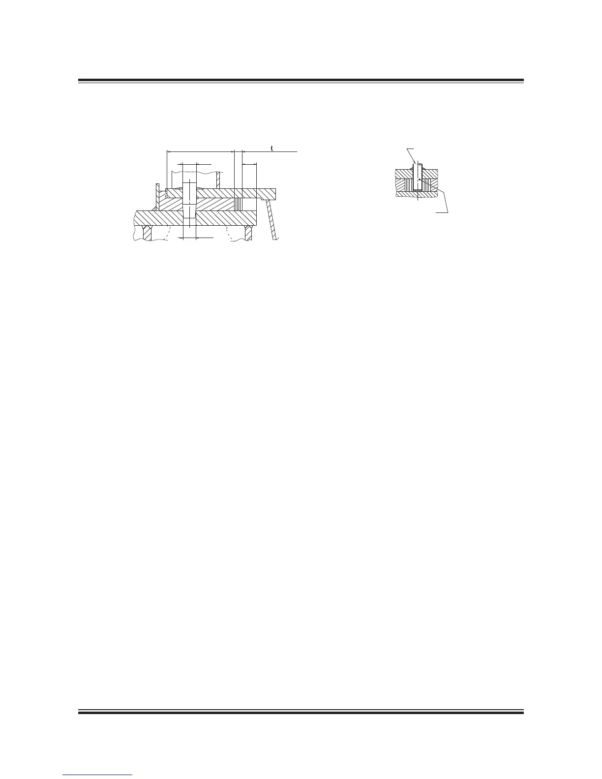
Fig. 5.12.01: Arrangement of epoxy chocks and holding down bolts
178 57 44-4.0
##
-X
!FTERæCURINGæOFæEPOXYæCHOCKS
THEæALIGNMENTæSCREWSæAREæTOæBE
LOOSENEDæAæCOUPLEæOFæTURNSæSOæASæ
TOæBEæCLEARæOFæTHEæTOPæPLATE
""
æTOæææENGINE
%FFECTIVEæ
 Loading...


