MAN B&W 5.18
Page 5 of 8
MAN Diesel
198 53 208.2MAN B&W S70MC, S70MC-C/ME-C/ME-GI, L70MC-C/ME-C,
S60MC, S60MC-C/ME-C/ME-GI/ME-B, L60MC-C/ME-C,
S50MC, S50MC-C/ME-C/ME-B, S46MC-C/ME-B, S42MC,
S40MC-C/ME-B, S35MC, S35MC-C/ME-B, L35MC, S26MC
178 22 396.0
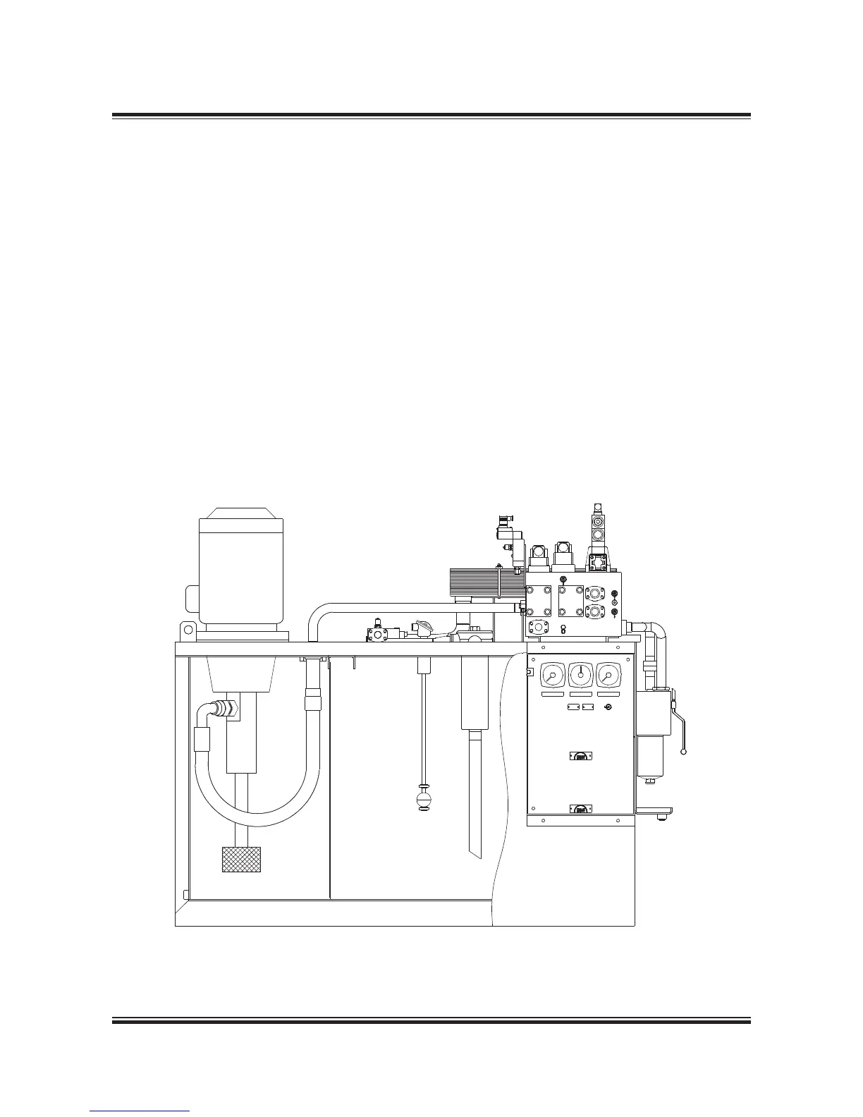
Fig. 5.18.06: Hydraulic Power Unit for MAN Diesel’s Alpha CP propeller, the servo oil tank unit
Hydraulic Power Unit for Alpha CP propeller
The servo oil tank unit, the Hydraulic Power Unit
for MAN Diesel’s Alpha CP propeller shown in Fig.
5.18.06, consists of an oil tank with all other com-
ponents top mounted to facilitate installation at
yard.
Two electrically driven pumps draw oil from the oil
tank through a suction filter and deliver high pres-
sure oil to the proportional valve.
One of two pumps are in service during normal
operation, while the second will start up at power-
ful manoeuvring.
A servo oil pressure adjusting valve ensures mini-
mum servo oil pressure at any time hereby mini-
mizing the electrical power consumption.
Maximum system pressure is set on the safety
valve.
The return oil is led back to the tank via a thermo-
static valve, cooler and paper filter.
The servo oil unit is equipped with alarms accord-
ing to the Classification Society’s requirements
as well as necessary pressure and temperature
indicators.
If the servo oil unit cannot be located with maxi-
mum oil level below the oil distribution ring, the
system must incorporate an extra, small drain
tank complete with pump, located at a suitable
level, below the oil distributor ring drain lines.
 Loading...


