EasyManuals Logo
Home>Parker>Servo Drives>P Series

Parker P Series User Manual

Parker P Series
316 pages
To Next Page IconTo Next Page
To Previous Page IconTo Previous Page
Page #104 background imageLoading...
Page #104 background image
Parker Hannifin
P Series User Guide 102
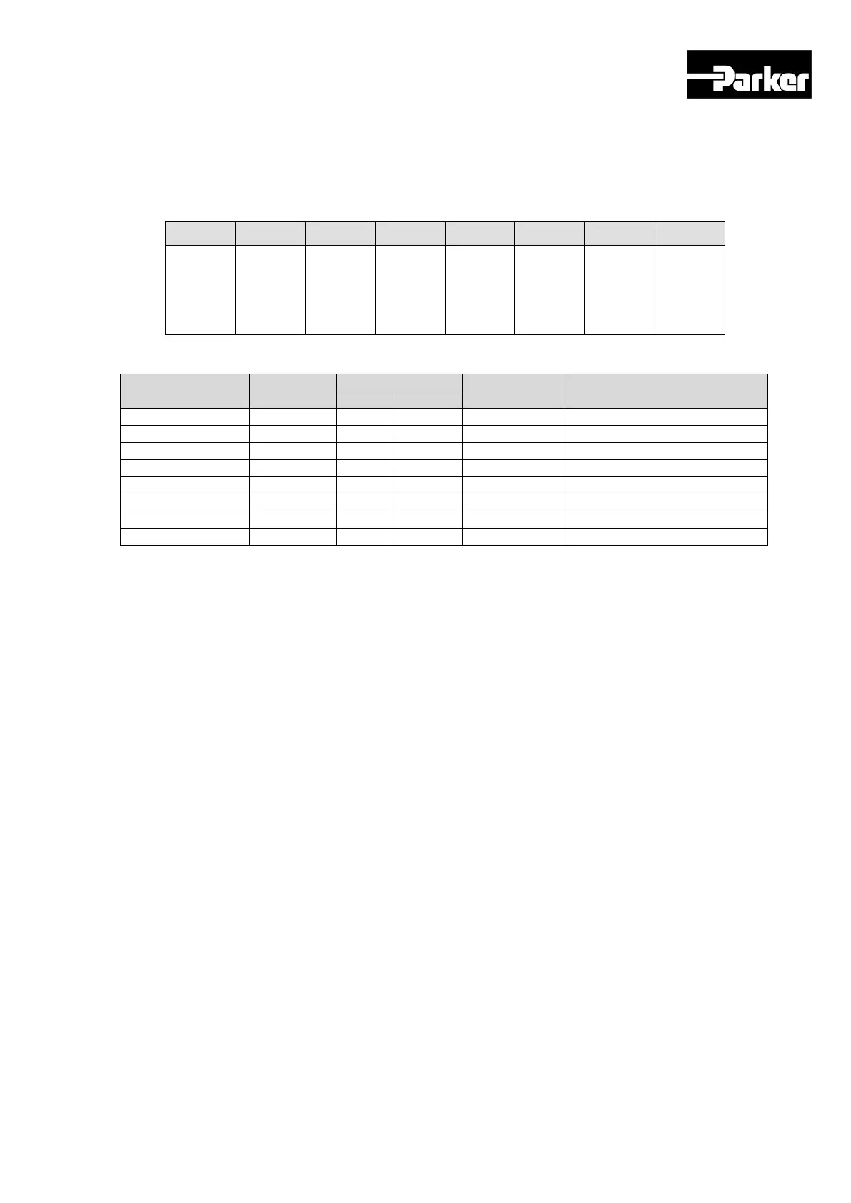
Example of Digital Output Allocation
The table below shows an example of allocating input signals. Please note the set
values of 0x2210~0x2217.
DO#1
DO#2
DO#3
DO#4
DO#5
DO#6
DO#7
DO#8
ALARM
(CONT
ACT B)
RDY
(CONT
ACT A)
BRAKE
(CONT
ACT B)
INPOS1
(CONT
ACT A)
ORG
(CONT
ACT A)
EOS
(CONT
ACT A)
TGON
(CONT
ACT A)
TLMT
(CONT
ACT A)
CN1
Pin number
Set
Parameter
Bit
Set value Content
15
7~0
DO # 1 (35,36)
0x2210
1
0x02
0x8002
ALARM (Contact B)
DO # 2 (37,38)
0x2211
0
0x03
0x0003
RDY (Contact A)
DO # 3 (39,40)
0x2212
1
0x01
0x8001
BRAKE (Contact B)
DO # 4 (41,42)
0x2213
0
0x05
0x0005
INPOS1 (Contact A)
DO # 5 (43,44)
0x2214
0
0x10
0x0010
ORG (Contact A)
DO # 6 (45,46)
0x2215
0
0x11
0x0011
EOS (Contact A)
DO # 7 (47,48)
0x2216
0
0x0A
0x000A
TGON (Contact A)
DO # 8 (49,50)
0x2217
0
0x06
0x0006
TLMT (Contact A)
Table 59. Example of Signal Output Allocation
4.5.3 Using User I/O
User I/O refers to a portion of I/S provided by the drive used for users purposes other
than the purpose of controlling the drive. All contacts provided through I/O connector
can be used as User I/O.
If the number of User I/O required is small, you can use the drive’s I/O connector
instead of using additional I/O modules, resulting in cost reduction.
This drive provides up to 16 input signals and 8 output signals as user I/O.
www.comoso.com

Table of Contents

Questions and Answers:

Question and Answer IconNeed help?

Do you have a question about the Parker P Series and is the answer not in the manual?

Parker P Series Specifications

General IconGeneral
BrandParker
ModelP Series
CategoryServo Drives
LanguageEnglish

Related product manuals