Parker Hannifin
P Series User Guide 67
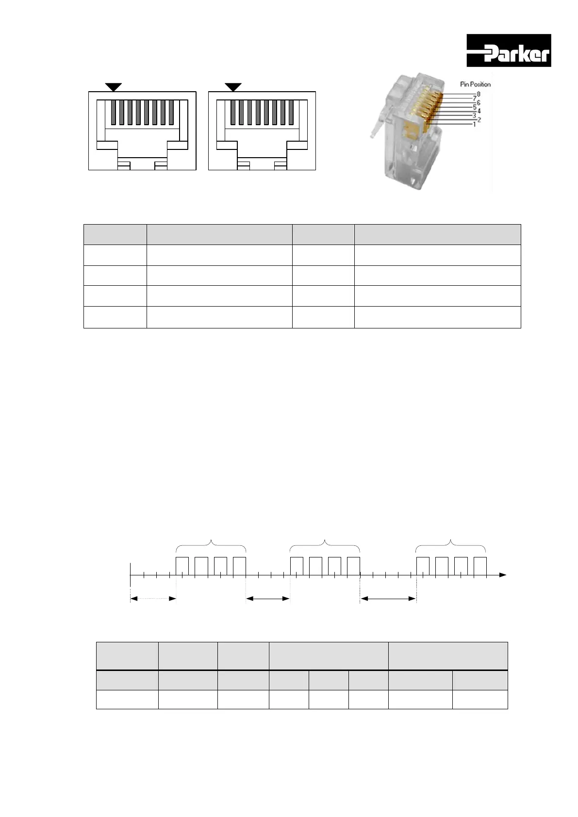
1
8
1
8
OUT IN
Pin arrangement viewed from the front
side of the drive
Pin arrangement viewed from the
connector
Pin No. Pin Function Pin No. Pin Function
1 Not Used 5 TXD+
2 Not Used 6 RXD-
3 RXD+ 7 Not Used
4 TXD- 8 Not Used
Table 21. RS-422 Connector Pin Description
NOTE ) As for IN connector, 5V voltage is output to Pin No. 7(+5V) and Pin No. 8(GND), to
supply power to the handy loader. Use for any other purpose is not allowed, and do
not connect Pin No. 7 and Pin No. 8 when wiring.
NOTE ) Connect TXD+ and TXD-, RXD+ and RXD- using twisted pair.
NOTE ) TXD and RXD of the above table is defined based on the servo drive.
4.2.3 Packet Structure
Maximum length of transmission/reception packet of MODBUS-RTU is 256 Byte. Please
make sure the total length of transmission/reception packet does not exceed 256 byte.
To classify packets, MODBUS-RTU Communication Mode requires empty spaces of at
least 3.5 characters at the starting point and the end point.
to
Packet1 Packet2 Packet3
at least 3.5 char at least 3.5 char 4.5 char
Transmission Packet Structure
Additional
Address
Functio
n Code
Data Error Check
Byte 0 1 2 . . n-1 n
description Node ID Function Data . . CRC(MSB) CRC(LSB)
Table 22. RS-422 Transmission Packet Structure
Reception Packet Structure

 Loading...


