Parker Hannifin
P Series User Guide 60
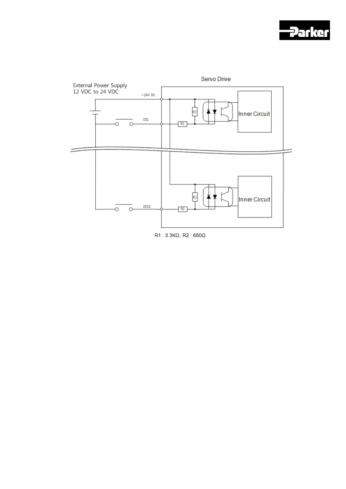
Please see “ 4.5 I/O Signals Setting “ for signal allotment and contact point change of
input contact points. The service rating is DC12V~ DC 24V.
Figure 20. Example of Digital Input Signal Wiring
Example of Digital Output Signal Wiring
Input contact point can be set at Contact Point A or B, depending on the characteristics of
each signal. Each input contact point can be allotted to 19 functions.
Please see “ 4.5 I/O Signals Setting “ for signal allotment and contact point change of
input contact points.
As transistor switches are used, over voltages/current may cause damage. Please
exercise caution. The service rating is DC 24V ±10%, 120[㎃].
 Loading...


