Parker Hannifin
P Series User Guide 167
6.11 Absolute Encoder Data Transmission
When absolute encoder data is requested, the absolute encoder data is transmitted to the host
controller through the encoder output signals AO and BO, in the form of quadrature pulse.
The encoder output pulse is output at the speed of 500[Kpps].
The drive, when the ABSRQ signal is input, first transmits the multi-turn data, followed by
transmission of single-turn data. (See “ 4.5 I/O Signal Setting “)
Absolute Data Transmission/Reception Sequence
A. When the host controller is ready to receive the data, set the ABSRQ signal to ON.
The ABSRQ signal can be input through digital input or ABSRQ bit of drive control input 2
[0x2120]. (See “ 4.3 Communication Address Table “)
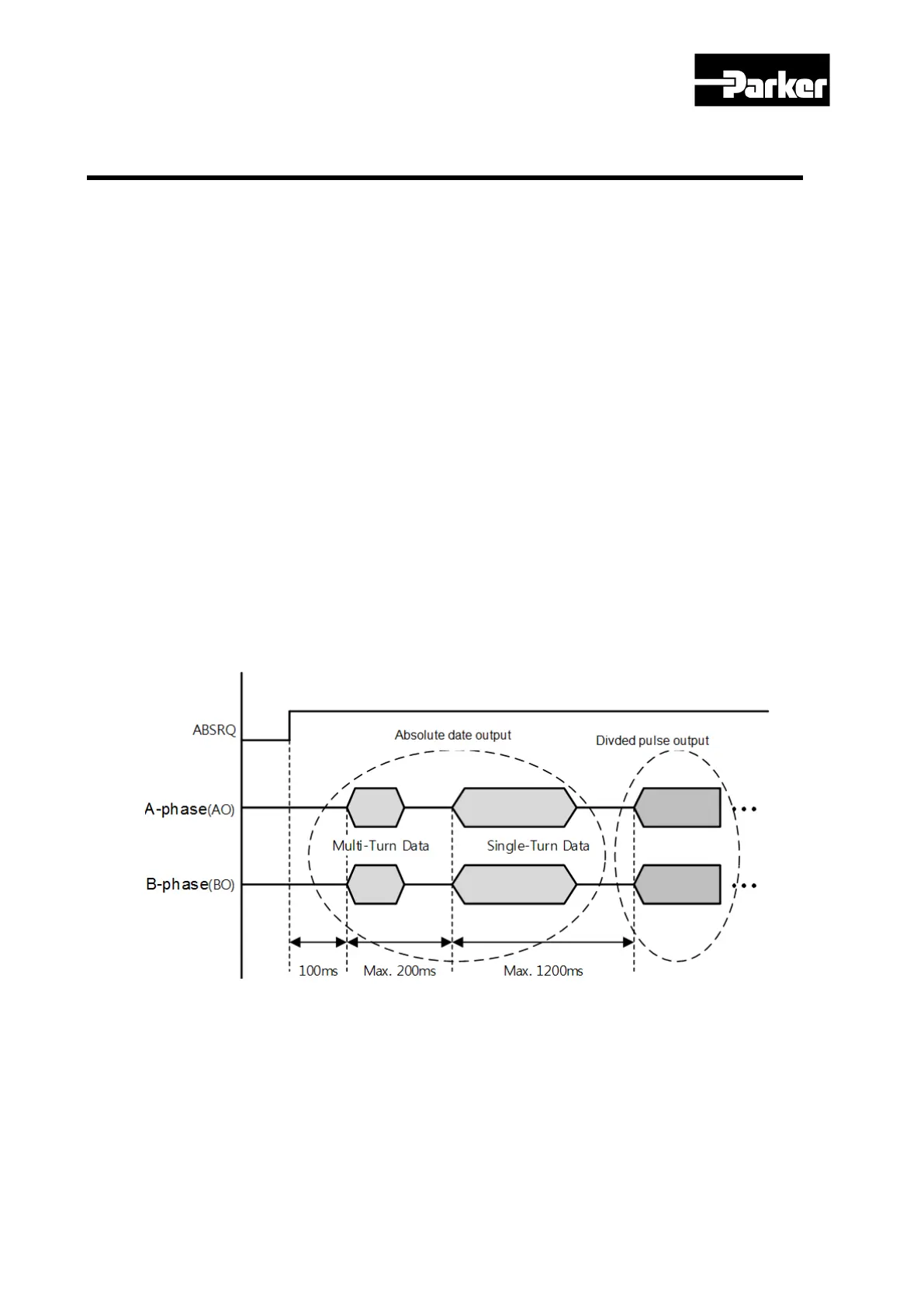
B. When the drive receives the ABSRQ signal, it prepares for encoder data transmission after
about 100[ms] delay.
C. The drive transmits the multi-turn data for up to 200[ms]. During the 200[ms] after the
multi-turn data transmission begins, the drive prepares for transmission of single-turn data.
D. The drive transmits the single-turn data for up to 1200[ms]. The output data at this time
has the vale determined under consideration of the number of encoder output pulses
(division ratio). 200[ms] after the single-turn data transmission begins, the drive goes back
to the normal encoder output signal.
Figure 51. Absolute Encoder Data Sequence

 Loading...


