Parker Hannifin
P Series User Guide 127
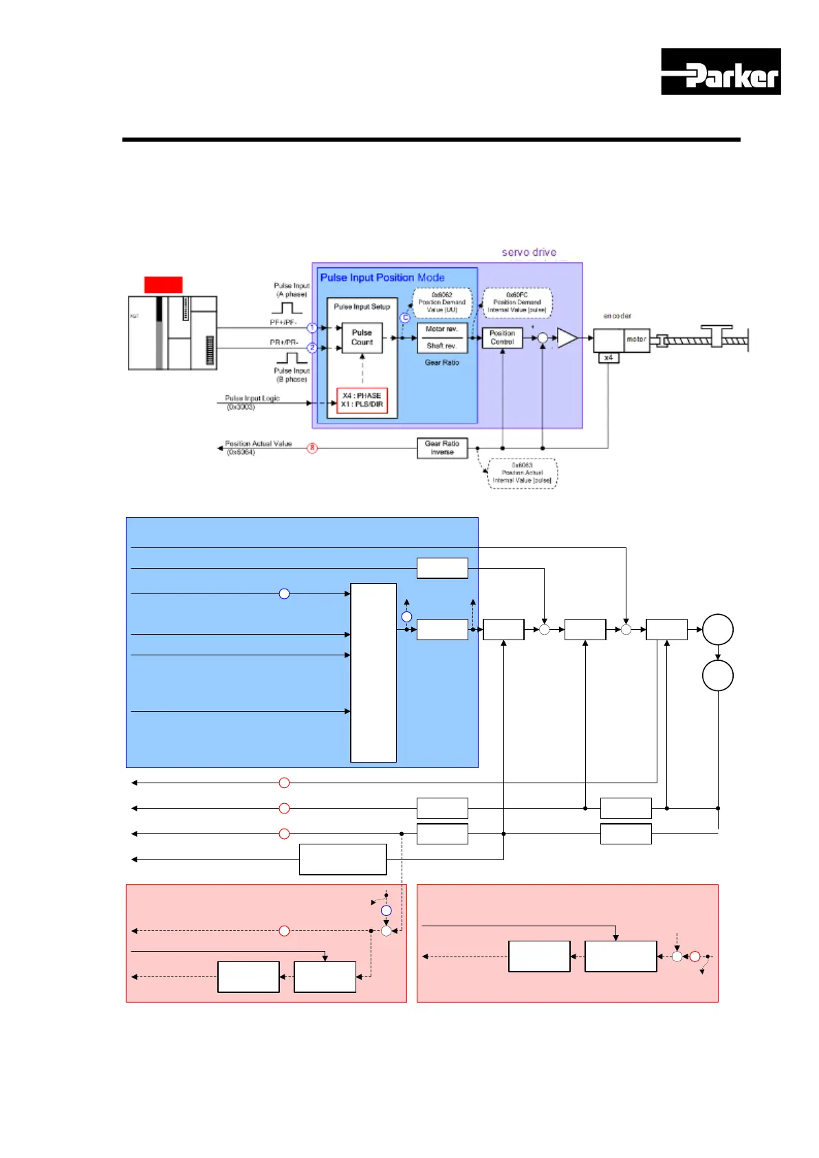
6.1 Pulse Input Position Operation
You can operate pulse input-type position control using a host controller with position
determination function.
To do this, the control mode [0x3000] should be set to 1.
The figure below shows the internal block diagram of pulse input-type position control
mode.
Torque Offset (0x60B2)
Velocity Offset (0x60B1)
Torque Actual Value (0x6077)
Pulse Input Logic (0x3003)
Pulse Input Filter (0x3004)
Control Mode (0x3000)
Velocity Actual Value (0x606C)
Position Actual Value (0x6064)
Pulse
Input
Setup
Position
Control
Velocity
Control
Torque
Control
+
+
+
+
M
Gear Ratio
Position Demand
Value (0x6062)
Enc.
Velocity
Calculation
Position
Calculation
Gear Ratio
Inverse
Gear Ratio
Inverse
Position Actual Internal
Value (0x6063)
Position Demand Internal
Value (0x60FC)
Control Mode : Pulse Input Position
6
7
8
C
Pulse Input ( PF+/PF- , PR+/PR- )
Gear Ratio
Following Error Actual Value (0x60F4)
Following Error Window (0x6065)
Following
Error Window
Comparator
Following
Error TimeOut
(0x6066)
Position Demand
Value (0x6062)
C
+
-
Following Error in
Statusword (0x6041.13)
Following Error
9
Position Window (0x6067)
Position
Reached Window
Comparator
Position
WindowTime
(0x6068)
Trajectory
Generator
ePosition
-
Target Reached in
Statusword (0x6041.10)
Position Reached
8
Position Actual
Value (0x6064)
+
Pulse Output (A/B/Z Phase)
Encorder Output Pulse
Regeneration
1
Figure 41. Pulse Input Position Operation

 Loading...


