Home
Parker
Servo Drives
P Series
Parker P Series User Manual
5
of 1
of 1 rating
316 pages
Give review
Manual
Specs
To Next Page
To Next Page
To Previous Page
To Previous Page
Loading...
Parker Hannifin
P
S
eries User G
uide
50
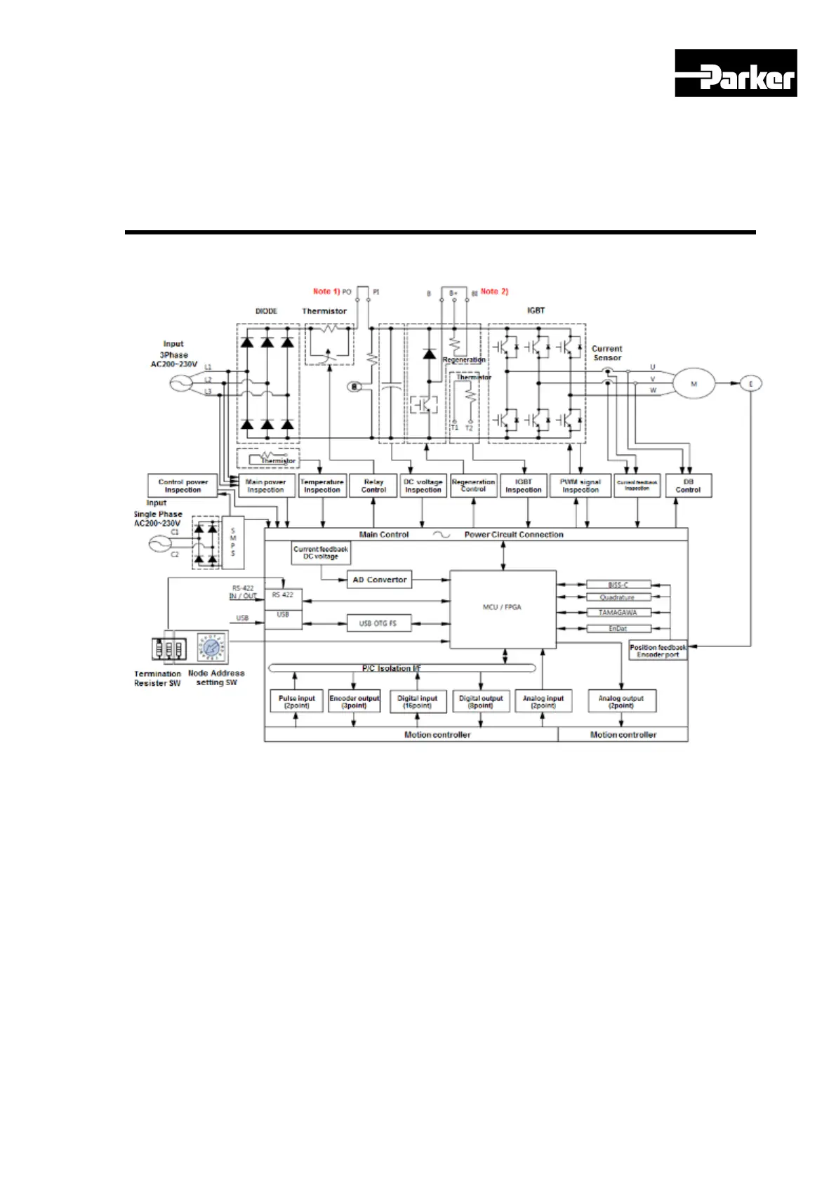
3.10
Drive Blocks
3.10.1 Drive B
lock
Figure 17
.
PD Dr
ive
Bloc
k
D
iagram
Note
1) W
hen
using DC reactor, please conne
ct with PO, PI.
Note 2)
W
hen using external recovery resis
tance, remove the shorting pin
s B, BI and then
connect with the B+, B pins.
www.comoso.com
51
53
Table of Contents
Default Chapter
3
Table of Contents
3
Table of Figures
8
Table of Tables
10
Important User Information
15
Change Summary
16
1 Introduction
17
P Series Products Overview
18
Table 1. Available Control Mode
18
Figure 1. PD Drive Names
19
Input Power
19
P Series Features
19
PD Drive Names
19
Figure 2. 400W Drive Front Description
20
Front Panel Description of Representative Drives
20
Table 2. Output Power Level
20
Figure 3. 1000W Drive Front Description
21
Figure 4. 3500W Drive Front Description
21
Figure 5. PM Motor Names
22
PM Motor Names
22
Compatible Parker Product
23
Assumptions of Technical Experience
23
2 Mechanical Installation
24
Environment
25
Table 3. Drive Installation Environment
25
Dimensions
26
PD Drive Dimensions (PD-04Xx to PD-35Xx)
26
Figure 6. PD Drive Dimensions
26
Table 4. PD Drive Dimensions
26
PM Motor Dimensions (FAL Series)
27
Figure 7. PM-FAL Series Motor Dimension
27
Table 5. PM-FAL Series Motor Dimension
27
PM Motor Dimensions (FBL Series)
28
Figure 8. PM-FBL Series Motor Dimension
28
Table 6. PM-FBL Series Motor Dimension
28
PM Motor Dimensions (FCL Series)
29
Figure 9. PM-FCL Series Motor Dimension
29
Table 7. PM-FCL Series Motor Dimension
29
PM Motor Dimensions (FE Series)
30
Figure 10. PM-FE Series Motor Dimension
30
Table 8. PM-FE Series Motor Dimension
30
PM Motor Dimensions (FF Series)
31
Figure 11. PM-FF Series Motor Dimension
31
Table 9. PM-FF Series Motor Dimension
31
Weight
32
Mounting Guidelines
32
Cable Routing
32
Panel Mounting
32
Table 10. PD Drive Weight
32
Figure 12. PD-04P Mounting Information
33
Figure 13. PD-10P Mounting Information
33
Preventing Excessive Impact
34
Combining with Load Device
34
Figure 14. PD-35P Mounting Information
34
Pulley Combining
35
Table 11. Pulley Combining Information
35
3 Electrical Installation
36
Installation Safety Requirements
37
Precautions
37
Auto-Configuration for Encoders
37
System Installation Overview
37
Power Supply
38
Power Circuit Electronics Specification
38
Figure 15. System Installation Overview
38
Table 12. Power Circuit Electronics Specification
38
Multiple Drive Installations
39
Drive Node Address Setting
39
Table 13. Drive Node Address Setting
39
Terminating Resistance Setting
40
Brake Relay (Optional)
40
Dynamic Brake
40
Signal Output Function Setting
41
Figure 16. Dynamic Brake Sequence
41
Table 14. Dynamic Brake Related Objects
41
Regeneration Protection
42
Table 15. Regeneration Related Objects
42
Table 16. Internal Resistor Setting
43
External Resistor Setting
45
Other Consideration
46
Table 17. External Regeneration Resistor Setting
46
Drive Status Indicators
47
PD Drive Alarm Code List
48
Table 18. PD Drive Alarm Code List
48
PD Drive Warning Code List
49
Connector Descriptions
49
Table 19. PD Drive Warning Code List
49
Installation Test
51
Drive Blocks
52
Figure 17. PD Drive Block Diagram
52
Wiring
53
Power
53
Figure 18. Drive Wiring Example
53
Feedback Signal
55
I/O Signal Wiring
60
Figure 19. I/O Signal Wiring
61
Figure 20. Example of Digital Input Signal Wiring
62
Figure 21. Example of Digital Output Signal Wiring
63
Figure 22. Example of Analog Input Signal Wiring
63
Pulse Heat Signal
64
Figure 23. Example of Analog Output Signal Wiring
64
Figure 24. Example of Pulse Heat Signal Wiring
64
Figure 25. Example of Open Collector Pulse Input Signal Wiring
65
Figure 26. Example of NPN Open Collector Pulse Command Wiring
65
4 Communications and I/O
66
Overview
67
Communication
67
Figure 27. RS-422 Multi-Drop Connection Example
67
Establishing Communication
68
Table 20. RS-422 Terminal Specification
68
Terminal Configuration
68
Packet Structure
69
Table 21. RS-422 Connector Pin Description
69
Table 22. RS-422 Transmission Packet Structure
69
Table 23. RS-422 Reception Packet Structure
70
Table 24. Protocol Packet Code Description
70
Protocol Command Code Description
71
Table 25. Exception Code Description
71
Table 26. Read Holding Register
75
Table 27. Example of Reading Single Parameter
75
Table 28. Example of Reading Multiple Parameters
76
Table 29. Read Input Signal
76
Table 30. Example of Reading Drive Status
77
Table 31. Write Single Register
77
Table 32. Example of Write Single Register
77
Table 33.Write Multi Register
78
Table 34. Example of Writing Multiple Parameters
78
Communication Address Table
79
System Configuration Parameters
79
Control Parameters
80
Table 35. System Configuration Parameters
80
I/O Parameters
81
Table 36. Control Parameters
81
Speed Operation Parameters
82
Table 37. I/O Parameters
82
Miscellaneous Parameters
83
Table 38. Speed Operation Parameters
83
Advanced Control Parameters
84
Monitoring Parameters
84
Table 39. Miscellaneous Parameters
84
Table 40. Advanced Control Parameters
84
Procedures and Alarm History
85
Rd Party Motor Parameters
85
Table 41. Monitoring Parameters
85
Table 42. Procedures and Alarm History
85
Cia402 Parameters
86
Table 43. 3 Rd Party Motor Parameters
86
Index Related Parameters
88
Table 44. Cia402 Parameters
88
Index00~63 Internal Variable Communication Address
89
Table 45. Index Related Parameters
89
Table 46. Index Variable Communication Address
89
I/O
90
Digital I/O
90
Table 47. Example of Internal Variable of Index00
90
Table 48. Digital Input Signal Description
93
Analog I/O
94
Table 49. Digital Output Signal Description
94
Pulse Heat Input
95
Encoder Output
95
Table 50. Analog Input Signal Description
95
Table 51. Analog Output Signal Description
95
Table 52. Pulse Train Input Signal Description
95
Table 53. Encoder Output Signal Description
96
I/O Signal Setting
97
Allocating Digital Input Signals
97
Table 54. Encoder Output Signal of Open Collector Method
97
Table 55. Encoder Output Related Objects
97
Figure 28. Allocating Digital Input Signals
98
Table 56. Allocating Digital Input Related Objects
99
Allocating Digital Output Signals
101
Table 57. Example of Signal Input Allocation
101
Figure 29. Allocating Digital Output Signals
102
Table 58. Allocating Digital Output Related Objects
103
Using User I/O
104
Table 59. Example of Signal Output Allocation
104
Table 60. User Input Related Objects
106
Table 61. User Output Related Objects
107
Table 62. Physical Output Descriptions
108
Table 63. Bit Mask Descriptions
108
5 Tuning
109
Servo Tuning Overview
110
Position Variable Overview
110
Commanded Position
110
Figure 30. Commanded Position
110
Actual Position
111
Servo Response Overview
111
Stability
111
Position Response Types
111
Performance Measurements
112
Automatic Gain Tuning (Off-Line)
112
Figure 31. Position Response Types
112
Figure 32. Control Loop Block Diagram
113
Related Objects
113
Table 64. Auto Tuning Related Objects
113
Automatic Gain Tuning (On-Line)
114
Changed Parameters after Tuning
114
On-Line Auto Tuning Object
115
Setting System Rigidity When On-Line Auto Tuning
116
On-Line Auto Tuning Adaption Speed
116
Manual Gain Tuning
117
Speed Controller Tuning
117
Position Controller Tuning
117
Vibration Control
118
Related Object
118
Figure 33. Vibration Control
118
Setting Vibration Suppression Filter(0X2515)
119
Filters
119
Related Objects
119
Figure 34. Meaning of Notch Filter
119
Adaptive Filter
120
Related Objects
120
Figure 35. Adaptive Filter Diagram
120
Table 65. Notch Filter Related Objects
120
Table 66. Adaptive Filter Related Objects
120
Analog Monitor
121
Related Objects
121
Figure 36. Analog Monitor
121
Analog Monitor Output Mode(0X2220) Setting
122
Analog Monitor Channel 1 Setting (0X2221)
122
Figure 37. Analog Monitor Output Setting
122
Table 67. Analog Monitor Related Objects
122
Setting Example
123
Figure 38. Setting Example
123
Table 68. Analog Monitor Channel Setting
123
Gain Conversion
124
Gain Group Conversion
124
Table 69. Gain Conversion Description
124
Related Objects
125
P/PI Control Conversion
125
Table 70. Gain Conversion Related Objects
125
Figure 39. P/PI Control Conversion
126
Figure 40. Example of P/PI Conversion
127
Table 71. P/PI Control Related Objects
127
6 Command Reference
128
Pulse Input Position Operation
129
Figure 41. Pulse Input Position Operation
129
Function Setting of Pulse Input Logic
130
Related Objects
130
Table 72. Pulse Input Logic Related Objects
131
Block Diagram
132
Figure 42.Inner Block Diagram under the Pulse Input Position
132
Function Setting of PCLEAR
133
Function Setting of Pulse Input Filter
133
Table 73. Pulse Input Filter Related Objects
133
Table 74. Function Setting of PCLEAR
133
Figure 43. Velocity Controller Inner Block Diagram
134
Related Objects
134
Function Set of Velocity Command Switch
135
Table 75. Related Objects for Velocity Control
135
Analog Velocity Command
136
Analog Velocity Command Scale
136
Table 76. Related Objects for Analog Velocity Command
136
Digital Command Scale
137
Table 77. Speed Setting by Digital Input Signal
137
Velocity Control
133
Torque Control
138
Analog Torque Command Scale
140
Figure 44. Torque Controller Inner Block Diagram
140
Speed Setting in Torque Control
141
Homing
142
Homing Methods
142
Figure 45. Homing Function
142
Related Objects
143
Table 78. Homing Methods
143
Table 79. Homing Related Objects
143
Electronic Gear Setting
154
Electronic Gear
154
Example of Electronic Gear Setting
156
Speed Control Setting
157
Smooth Acceleration/Deceleration
157
Figure 46. Speed Control
157
Table 80. Examples of Gear Setting
157
Servo Lock Function
158
Related Signal
158
Figure 47. Smooth Acceleration and Deceleration
158
Table 81. Servo Lock Function
158
Position Control Setting
159
Position Command Filter
159
Table 82. Servo Lock Function Related Objects
159
Figure 48. Position Command Filter
160
Table 83. Position Command Filter Related Objects
160
Signals Related with Position Control
161
Table 84. Position Control Related Objects
161
Limit Setting
162
Forward/Reverse Limit Setting
162
Table 85. Limit Setting Related Objects
162
Brake Output Signal Function Setting
163
Figure 49. Brake Output Function
163
Torque Limit Setting
165
Figure 50. Torque Limit
168
Table 86. Torque Limit Related Objects
168
Absolute Encoder Data Transmission
169
Figure 51. Absolute Encoder Data Sequence
169
Figure 52. Touch Probe Function
170
Touch Probe Function
170
Table 87. Touch Probe Function Related Objects
171
Figure 53. Touch Probe Function Timing Diagram
172
7 Procedure
173
Procedure Function
174
Manual Jog Operation
174
Table 88. Procedure Function
174
Program Jog Operation
175
Figure 54. Program Jog Operation
175
Table 89. Procedure Function Related Objects
175
Alarm Record Detection
176
Table 90. Program Jog Operation Related Objects
176
Automatic Gain Tuning
177
Index Pulse Probing
177
Table 91. Alarm Detection Related Objects
177
Absolute Encoder Reset
178
Table 92. Index Pulse Probing Related Objects
178
Instantaneous Maximum Torque Reset
179
Phase Current Offset Tuning
179
Table 93. Absolute Encoder Reset Related Objects
179
Table 94. Instantaneous Maximum Torque Reset Related Objects
179
Software Reset
180
Commutation
180
Table 95. Phase Current Offset Related Objects
180
Table 96. Commutation Related Objects
180
8 Indexer
181
Figure 55. Indexing Position Operation
182
Indexer Overview
182
Control Methods
182
Table 97. Indexing Position Operation Related Objects
183
Coordinate Setting
185
Figure 56. Internal Blocks of Indexing Position Mode
185
Index Structure
188
Table 98. Index Structure
188
Indexing Position Operation
189
Concept of Index
189
Absolute and Relative Move
194
Registration Absolute and Relative Move
195
Blending Absolute and Relative Move
196
Rotary Absolute and Relative Move
196
Rotary Shortest Move
197
Rotary Positive and Negative Move
198
Functions of Index Input Signal
199
Functions of Index Output Signal
202
Analog Speed Override
203
Figure 57. Analog Speed Override
203
Table 99. Analog Speed Override Related Objects
203
9 Object
204
Object Dictionary
205
Data Type
205
General Objects
205
Table 100. Object Dictionary Data Type
205
Table 101. Hardware Version
206
Table 102. Software Version
206
Table 103. Store Parameters
207
Table 104. Restore Parameters
208
Table 105. Identity Object
208
Manufacturer Specific Objects
209
Table 106. Encoder Type Object
209
Table 107. Encoder Pulse Per Revolution
210
Index Objects
264
Table 108. Touch Probe Functions
277
Table 109. Touch Probe Status
278
Table 110. Digital Input Status
280
Table 111. Physical Output Descriptions
281
Table 112. Bit Mask Descriptions
281
Table 113. Supported Modes
282
10 PM Motors
283
Specification
284
Table 114. PM-FAL Series Features
284
Table 115. PM-FBL Series Features
284
Table 116. PM-Fclxxamxx Series Features
285
Table 117. PM-Fclxxdmxx Series Features
285
Table 118. PM-Fexxamxx Series Features
286
Table 119. PM-Fexxdmxx Series Features
287
Table 120. PM-Fexxgmxx Series Features
287
Table 121. PM-Fexxmmxx Series Features
288
Table 122. PM-Ffxxam/MMXX Series Features
288
FAL Series N-T Curves
289
Table 123. PM-Ffxxdm/Gmxx Series Features
289
FBL Series N-T Curves
290
Figure 58. FAL Series N-T Curves
290
FCL Series N-T Curves
291
Figure 59. FBL Series N-T Curves
291
Figure 60. FCL Series N-T Curves
293
FE Series N-T Curves
294
FF Series N-T Curves
299
Figure 61. FE Series N-T Curves
299
Figure 62. FF Series N-T Curves
301
11 Troubleshooting
302
Troubleshooting Guidelines
303
Servo Alarm and Check List
303
Servo Warning and Check List
309
Table 124. Servo Alarm Check List
309
Table 125. Servo Warning Check List
310
Appendix A Firmware Update
311
Using USB OTG
312
Using Drive Support Tool
313
5
Based on 1 rating
Ask a question
Give review
Questions and Answers:
Need help?
Do you have a question about the Parker P Series and is the answer not in the manual?
Ask a question
Parker P Series Specifications
General
Brand
Parker
Model
P Series
Category
Servo Drives
Language
English
Related product manuals
Parker P-38
2 pages
Parker P-38 Standard
3 pages
Parker 638 series
129 pages
Parker 590C
401 pages
Parker OEM750
96 pages
Parker Compax3
398 pages
Parker PSD1-SW1200
109 pages
Parker 591C
401 pages
Parker PD-04 Series
286 pages
Parker PM-FBL04AMK
286 pages
Parker Compumotor APEX615 Series
144 pages
Parker PSD1-S
31 pages

 Loading...


