Parker Hannifin
P Series User Guide 88
Table 47. Example of Internal Variable of Index00
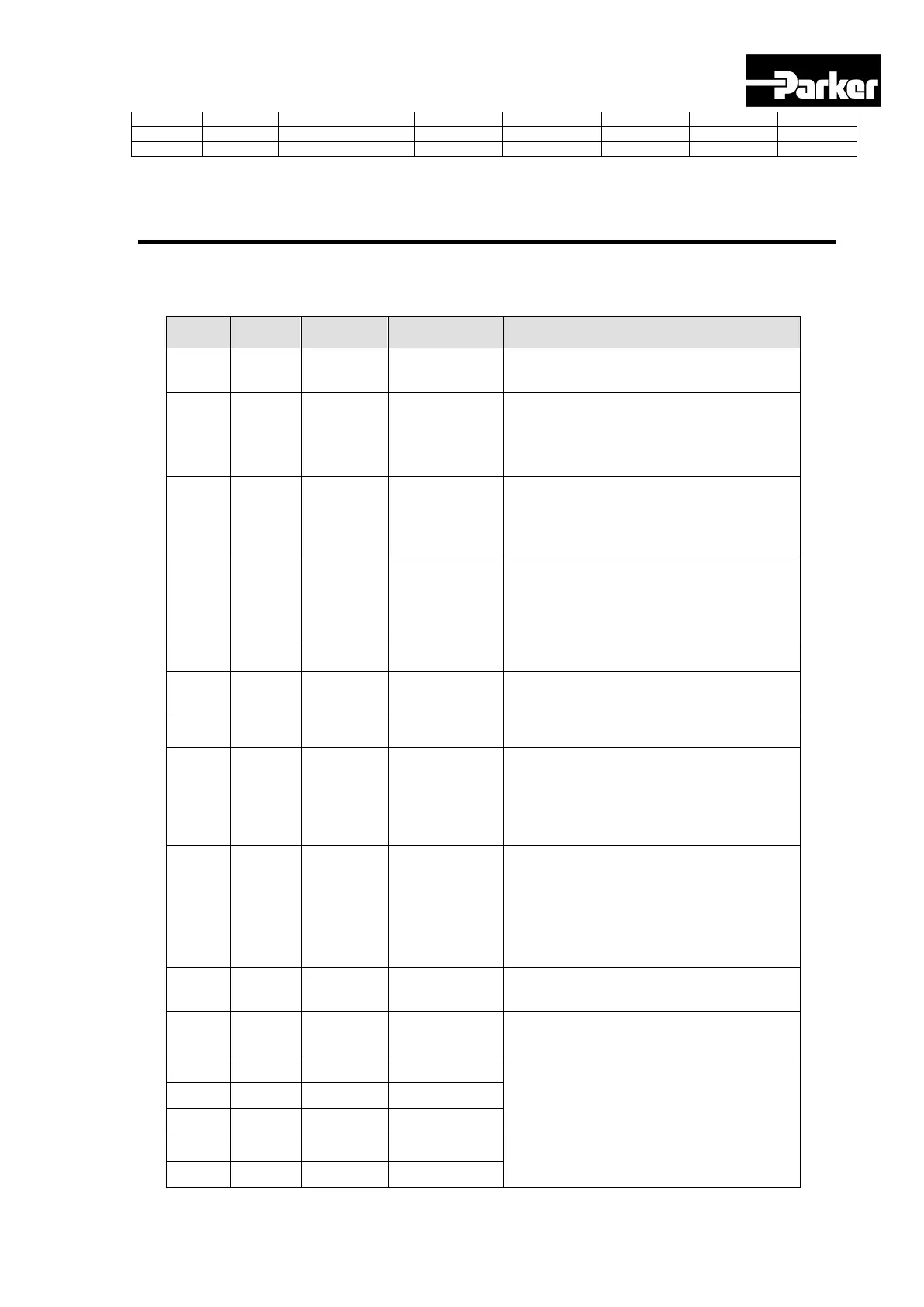
4.4.1 Digital I/O
Digital Input Signals (I/O Connector)
Pin No. Name Allotment Description Function Details
21, 11 +24V DC 24V
DC 24V
INPUT
COMMON
12 DI1 SVON Servo ON
When the SVON signal is ON, the
product is operational (Servo ON)
When the signal is OFF, the motor goes
into the free run state.
13 DI 2 POT
No
forward(CCW)
rotation
The motor is stopped so that the actuator
cannot rotate forward more than the set
motion window [0x2013] The set value
determines how it stops.
14 DI3 NOT
No
backward(CW
)
rotation
The motor is stopped so that the actuator
cannot rotate reverse more than the set
motion window [0x2013] The set value
determines how it stops.
15 DI4 A-RST Alarm reset Turns off the Servo alarm.
16 DI 5 START
Initiate
operation
Initiates operation to the index position
operation.
17 DI 6 STOP Stop servo Stops operation.
18 DI 7 REGT
Post-sensor
operation
If the index type is registration absolute or
registration Relative, when the REGT
signal is on, the speed and distance is
changed to the preset speed and
distance.
19 DI 8 EMG
Emergency
stop
When the EMG signal is on, the servo
makes an emergency stop, generating
‘W-80’. [0x2013] The set value
determines how it stops.
22 DI 9 HOME Origin Sensor
Home sensor input signal, used when
returning to the origin.
23 DI 10 HSTART
Initiate Origin
Operation
Initiates operation back to the origin
24 DI 11 ISEL0 Select Index 0
Select an index for operation among
index 0 to 63.
25 DI 12 ISEL1 Select Index 1
26 DI 13 ISEL2 Select Index 2
27 DI 14 ISEL3 Select Index 3
28 DI 15 ISEL4 Select Index 4

 Loading...


