Parker Hannifin
P Series User Guide 68
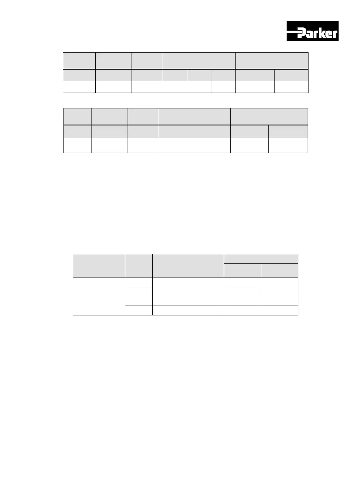
[Normal Response]
Additional
Address
Function
Code
Data Error Check
Byte 0 1 2 . . n-1 n
description Node ID Function Data . . CRC(MSB) CRC(LSB)
[Abnormal Response]
Additional
Functio
Data Error Check
Byte 0 1 2 3 4
descripti
on
Node ID
Function+
0x80
Exception code CRC(MSB) CRC(LSB)
Table 23. RS-422 Reception Packet Structure
Protocol Packet Code Descriptions
Node ID
This indicates the Node ID of the servo driver to transmit.
The Node ID of servo Drive can be configured with the external switch at the loader
window. The set Node ID can be viewed at parameter [0x2003].
Function Code
Function Codes under Modbus-RTU Standard supported by PD Drive are as follows.
Category
Comm
and
Descriptions
Usage
Read Write
PUBLIC Function
Code
0x03 Read Holding Registers ○
0x04 Read Input Register ○
0x06 Write Single Register ○
0x10 Write Multi Register ○
Table 24. Protocol Packet Code Description
Data
[Transmission] : In the case of Read Register command, Modbus address, number of
registers, and number of bytes, etc. are designated. In case of Write Register command,
Modbus address, number of bytes, and value to set, etc. are designated.
[Reception] : In the case of Read Register command, under normal response, Node ID
and Function Code are received as the same values as the transmitted values. The
value of each register is received in the order they were transmitted.
In the case of Write Single Register command, the same values as the transmitted
values are received. In the case of Write Multi Register, the starting address intended to
write the data in with the same values as the transmitted values and the number of
registers are received.
Abnormal response consists of Node ID, Error Code and Exception Code. Packet
structure of abnormal response is the same regardless of the function code.

 Loading...


