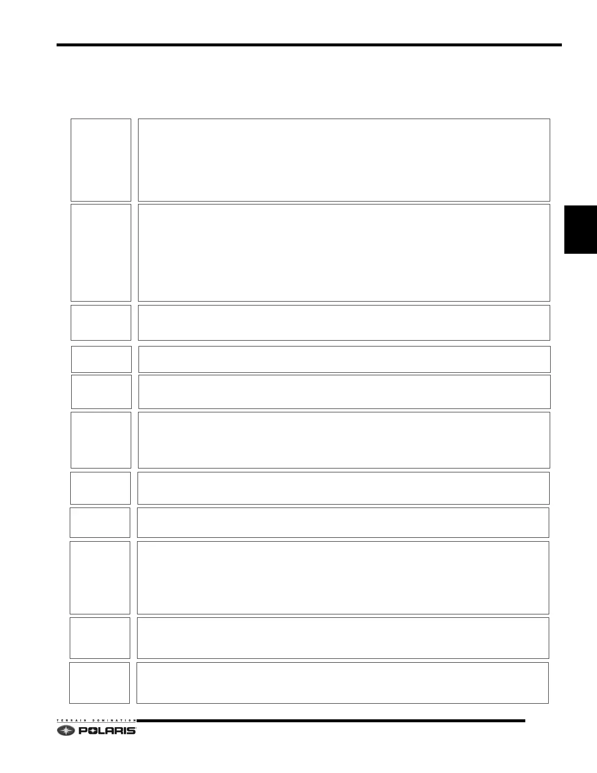
STEP 1
Preliminary
Checks
DOCUMENT THE BASICS
1. VIN
2. Vehicle Miles
3. Issue(s)
4. Vehicle / Engine Modifications (Non-approved modifications may cause performance/durability issues.)
5. Check unit against Unit Inquiry for any outstanding Service Bulletins or Team Tips
6. Type of fuel in the fuel tank / Fuel Selector Status
The fuel selector jumper wires or resistor plug must be set as outlined below based off of the type of fuel in the tank.
Fuel octane not known, < 91+ octane, or any 87+ octane oxygenated (ethanol, MTBE, etc, blended) fuel = 24 OHM Resistor
91+ octane non-oxygenated (non-ethanol) fuel = 160 OHM Resistor
STEP 2
Using
Digital
Wrench
DIGITAL WRENCH (DW)
1. Is DW the most current version? Check the DW update site (http://polaris.diagsys.com/modules.php?name=Downloads) to review and
download any available updates.
2. Connect DW to the vehicle. Are there any trouble code(s)? Document all of the trouble code(s), both historic and current. Use guided
diagnostics to troubleshoot current trouble code(s). Once repairs are made and trouble code(s) are cleared, do any return? Start the
engine and confirm trouble code(s) to not re-appear. If trouble code(s) re-appear, continue to troubleshoot issue using guided
diagnostics and Service Manual.
3. Review the ECU information for the vehicle. Does the ECU map match the vehicle’s configuration / fuel injector color and part
number? If not, reflash the ECU using the correct color-coded map / part number that matches the fuel injector color / part number
installed on the engine.
4. Is the vehicle subject to any Service Bulletins, or Team Tips where revised ECU reflash files have been made available? If so, verify
the Service Bulletin or Team Tip has been performed if required and the ECU information matches the revised reflash files.
STEP 3
Clutching
CLUTCHING
1. Do the drive clutch weights match what is specified for the elevation where the vehicle is operated? If not, install the specified drive
clutch weights based model specifications for the vehicle located in the appropriate Service Manual or Owner’s Manual Supplement.
2. Inspect drive belt deflection and adjust if required. Replace the belt if it is hour-glassed, shows heavy glazing or severely worn.
STEP 4
Throttle Lever
THROTTLE LEVER FREEPLAY
1. Check the throttle lever freeplay. Too much slack in the throttle cable can cause runability issues.
2. Is the throttle lever freeplay = .010 - .030 inches? If not, reset the freeplay to specification and retest vehicle.
STEP 6
EGT
Sensor
EXHAUST GAS TEMPERATURE SENSOR
1. Using the data display tool in Digital Wrench, monitor the EGT sensor function while the engine is running (vehicle raised off the
ground on a sled lift or track stand) at or above 3,000 RPM.
2. Does the exhaust gas temperature value change with changing throttle lever input after running the engine for 60 seconds at or
above 3,000 RPM?
3. If the EGT value does not change, inspect the sensor wiring and connections. If the wiring and connections are good, replace the
sensor and retest.
STEP 7
Exhaust
System
EXHAUST SYSTEM
1. Check exhaust system for leaks, missing, over-stretched damaged springs, and worn out seals. Replace components as required.
2. Remove the resonator and shake. Replace resonator if shaking reveals loose internal baffle plates.
STEP 8
Ignition
System
IGNITION SYSTEM
1. Insect the spark plug caps and spark plugs. Are the caps worn, oblong, or bent? Replace cap(s) as required.
2. Have the spark plug(s) worn into the top of the cap(s)? If so, replace both the affected spark plug and cap as required.
STEP 9
Exhaust
Valves
EXHAUST VALVES
1. Inspect VES system. Clean valve blades as outlined in the periodic maintenance table. Inspect valve bellows for tears, damage.
2. Inspect the exhaust valve solenoid vent system (discharge hose) for leaks or plugged / kinked hoses. Repair or re-route hoses /
connections as required. Verify outlet hoses is not freezing during operation. Inspect fittings at solenoid are not leaking.
3. Do the exhaust valves move as RPM increases? Test exhaust valve motion by installing a 1 inch piece of clear, fuel vent hose onto
each EV cap nut through the hole in each EV housing. Start the engine and increase the engine speed past 6,000 RPM to check for
proper valve operation.
4. Do both valves move at the same time / rate? If not, inspect one or both EV assemblies. Inspect for torn bellows, worn EV springs
and loose bellows cap nuts. Verify the EV base vent and cylinder holes are clean and free from carbon or heavy residue.
STEP 10
Pistons
PISTONS
1. With the exhaust valve assemblies removed from the cylinders, insert a piston wash light or use a flashlight to inspect the exhaust-
side of the pistons. Is heavy scoring, scratching or ring damage visible?
2. If piston skirt, or ring damage is visible through the exhaust valve slots, the pistons should be replaced and the cylinders inspected
and lightly honed with an Ammco 320 grit (or equivalent) NiCaSil oversize honing stone.
STEP 5
Fuel
System
FUEL SYSTEM
1. Using Digital Wrench, verify the fuel injector supply voltage is 16VDC when the engine is running.
2. Using the appropriate fuel pressure gauge (see Service Manual), verify the fuel pressure when the engine is running is 58 PSI (4BAR).
3. If the fuel pump voltage is good, but the fuel pressure low, replace the fuel filter and recheck fuel pressure.
STEP 11
Engine
ENGINE
1. Perform compression test.
2. Inspect crankshaft index.
3. Verify flywheel key has not sheared (flywheel out of index).
 Loading...


